
User Manual


32 06-DPP-UM-00147 02/12
+
C3
JP2
J3
J4
J2
JP1
JP3
2
4
1
3
1
3
4
6
7
9
10
12
VPP12-800
CLASS B
R
®
VDE
MODULE #2
MODULE #1
JP1/JP2
Connections
115/230
VAC
JP2
JP1
JP3
J4
J3
J2
9-28 VDC
9-28 VDC
21
43
21
43
21
43
21
43
2
1
21
2
1
21
21
21
Fuse (5x20mm)
AC: 0.25 A/250V Delay
DC: 1.0 A/250V Delay
Receive Transmit
RED BLK
BLU CLR
REDBLK
BLUCLR
EXT SYNC
SYNC SELECT
INT
EXT
GND
AC
DC
EARTH
EARTH
GND
L1
L2
+V
230 VAC
115 VAC
Connections
JP3
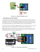
WIRING DIAGRAM
CAUTION! To avoid serious injury or damage,
disconnect electrical power before servicing this meter
b NO
b CM
b NC
a NO
a CM
a NC
I/O: RELAY
P.N. D020-1045-102
ISO-MOD
OUT (-)
IN (
+
)
I/O: 4-20 mA
P.N. D020-1045-100
ISO-MOD
JP2
JP1
INT PWR EXT PWR
FIGURE 3.9 TWO ISOMOD I/O MODULES INSTALLED
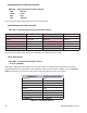
420 MA OUTPUT MODULE
The 4-20 mA Output Module interfaces with most recording and logging systems by transmitting an
analog current signal that is proportional to system ow rate. The 4-20 mA ISO-MOD may be congured
via jumper selections for either an internally powered (Figure 3.10B) or externally powered (Figure
3.10C) mode. Care must be exercised to not exceed the maximum load for a particular supply voltage.
See Figure 3.10A.
200
100
300
400
500
600
700
800
900
1000
1100
12 14 16 18 20 22 24 26 28
Supply Voltage (VDC)
Loop Load (Ohms)
Operate in the
Shaded Regions
Supply Voltage - 7 VDC
0.02
= Maximum Loop Resistance
FIGURE 3.10A MAXIMUM 420 MA LOADS