
User Manual


06-DPP-UM-00147 02/12 31
MODULE #2
MODULE #1
JP1/JP2
Connections
115/230
VAC
JP2
JP1
JP3
J4
J3
J2
9-28 VDC
9-28 VDC
21
43
21
43
21
43
21
43
2
1
21
2
1
21
21
21
Fuse (5x20mm)
AC: 0.25 A/250V Delay
DC: 1.0 A/250V Delay
Receive Transmit
RED BLK
BLU CLR
REDBLK
BLUCLR
EXT SYNC
SYNC SELECT
INT
EXT
GND
AC
DC
EARTH
EARTH
GND
L1
L2
+V
230 VAC
115 VAC
Connections
JP3
WIRING DIAGRAM
CAUTION! To avoid serious injury or damage,
disconnect electrical power before servicing this meter
MO
D
U
LE #2
MO
D
U
LE #1
J
P1
/
JP2
Connect
i
ons
115/23
0
V
A
C
J
P2
J
P
1
JP3
J
J
4
J3
J
2
9-2
8
VD
C
9-28 VD
C
2
1
4
3
2
1
4
3
2
1
4
3
2
1
4
3
2
1
2
1
2
1
2
1
2
1
2
1
F
use
(
5x20mm
)
A
C: 0.25 A/250V Dela
y
D
C: 1.0 A/250V De
l
ay
R
ece
i
ve Transm
it
R
E
D
B
LK
B
L
U
C
LR
RE
D
B
LK
B
L
U
C
LR
E
XT
S
YN
C
S
YN
C
SELE
C
T
I
NT
E
X
T
G
ND
A
C
D
C
E
A
R
TH
E
A
R
TH
G
N
D
L
1
L
2
+V
230
VA
C
115 VA
C
Connect
i
ons
J
P
3
W
IRING DIAGRAM
C
AUTI
O
N!
T
o avoi
d
serious injury or
d
amage,
d
isconnect electrical power before servicin
g
this meter
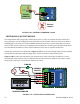
Master Meter Slave Meter Slave Meter
Master Meter
Set to Internal
Synchronization
Twisted Pair
Shield
(Connect One End
Only to Earth Ground)
Twisted Pair
Wire
Slave Meters
Set to External
Synchronization
Slave Meters
Set to External
Synchronization
FIGURE 3.8 DFX SYNCHRONIZATION CONNECTIONS
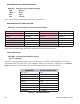
ISO MODULES
The DFX utilizes ISO-MODs for input and output functions. ISO-MODs are epoxy encapsulated electronic
input/output modules that are simple to install and replace in the eld. See Figure 3.9. All modules are
2,500 V optically isolated from DFX power and earth grounds. This eliminates the potential for ground
loops and reduces the chance of severe damage in the event of an electrical surge.
Three ISO-MOD options are available, including: 4-20 mA, dual-relay and rate pulse. The DFX supports
any two ISO-MOD input/output modules. All modules are eld congurable by utilizing the keyboard
interface. Field wiring connections to ISO-MODs are quick and easy using removable wiring terminals.
Conguration and connection of the various ISO-MODs are described on the following pages.
ISO MODULE REPLACEMENT
To remove an ISO-MOD, remove the two machine screws that secure the module in place and pull the
module straight out of the enclosure. A 10-pin connection is on the bottom of the module that mates
with the circuit board underneath. Installation of a module is simply the reverse operation of removal.
4-20 mA modules will require calibration parameters to be entered if the module is replaced. See Part 4
of this manual for instructions on entry of calibration parameters.