
User Manual


30 06-DPP-UM-00147 02/12
MULTIPLE METER INSTALLATIONS
The DFX ow meter contains a provision for synchronizing multiple DFX ow meters together. Synchro-
nization is required when more than one DFX ow meter is mounted on a common pipe or header sys-
tem. If meters are not synchronized, a phenomena called “cross-talk” can occur between meters, which
can lead to erroneous readings or no readings at all. Cross-talk results from the small dierences in trans-
mitted frequency generated from two or more dierent ultrasonic ow meters. By synchronizing the
transmitted ultrasonic energy, cross-talk caused by dierences in transmitted frequency is eliminated.
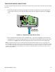
The DFX synchronization circuit is designed to interconnect up to four DFX ow meters over a cable
length of 100 feet (30 meters). Utilize 20-22 AWG twisted-pair shielded interconnection wire for this pur-
pose. See Figure 3.7.
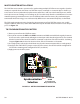
TO SYNCHRONIZE MULTIPLE METERS:
1) Remove power from the DFX ow meters.
2) Daisy-chain connect the EXTernal SYNChronization and GND terminal blocks together between
the meters to be synchronized, utilizing the twisted-pair cable described previously. The terminal
block is located on the circuit board that is mounted on the door of the DFX monitor. See Wiring
Diagram Figure 3.4, the decal on the inner door of the DFX monitor or schematic.
3) At a single point, connect the shield drain wire from the interconnection cable to earth ground.
4) Congure the SYNC SELECT jumpers on the DFX ow meters. One DFX should be congured for
INT and the remaining units congured for EXT (see below).
5) Apply power to the DFX system.
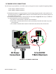
JP1/JP2
Connections
115/230
VAC
J4
J3
J2
9-28 VDC
9-28 VDC
43
2
1
21
21
21
21
Fuse (5x20mm)
AC: 0.25 A/250V Delay
DC: 1.0 A/250V Delay
Receive Transmit
RED BLK
BLU CLR
REDBLK
BLUCLR
EXT SYNC
SYNC SELECT
INT
EXT
GND
AC
DC
EARTH
EARTH
GND
L1
L2
+V
Synchronization
Selection
Twisted Pair
Shield
(Connect One End
Only to Earth Ground)
FIGURE 3.7 METER SYNCHRONIZATION DETAIL