
User Manual


06-DPP-UM-00147 02/12 13
PART 2 TRANSDUCER INSTALLATION
UNPACKING
After unpacking, it is recommended to save the shipping carton and packing materials in case the instru-
ment is stored or re-shipped. Inspect the equipment and carton for damage. If there is evidence of ship-
ping damage, notify the carrier immediately.
MOUNTING LOCATIONS
The transducers that are utilized by the DFX contain piezoelectric crystals for transmitting and receiv-
ing ultrasonic sound energy through the pipe wall in the case of the series DT9 transducer and from the
probe tip of the series DP7. Placement of the ultrasonic transducer is the most critical step in achieving
an accurate and reliable ow reading. All ow meters of this type rely on a full-pipe of uid that is owing
symmetrically (evenly) in the pipe. Flow in partially lled pipes and immediately downstream of elbows,
valves and pumps is unstable and will lead to unstable readings and non-linearity.
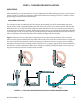
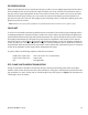
Figure 2.1 illustrates ve possible pipe congurations and recommends installation only in locations
where it can be guaranteed that the pipe will be lled at all times when ow measurements are required.
The two locations illustrated in the top two drawings may allow the meter to operate, but it is unlikely
that stable and accurate ow readings will be realized over a very large range of ow. Since products like
the DFX have software algorithms that assume a full-pipe of liquid, partially-lled pipes can lead to very
large ow measurement errors and should be avoided.
h
h
FIGURE 2.1 PIPE CONFIGURATIONS AND INSTALLATION RECOMMENDATIONS