DDFXD Doppler Ultrasonic Flow Meter FORM # 06-DPP-UM-00147 RUN Tel: 262-639-6770 Toll Free: 800-535-3569
TABLE OF CONTENTS SYMBOL EXPLANATIONS .................................................................................................6 QUICK-START OPERATING INSTRUCTIONS ...................................................................7 1 - TRANSDUCER LOCATION ...................................................................................................................7 2 - PIPE PREPARATION AND TRANSDUCER MOUNTING .......................................................................
APPENDIX ........................................................................................................................53 SPECIFICATIONS ...................................................................................................................................53 MENU MAPS ..........................................................................................................................................55 PIPE TABLES.....................................................................
FIGURES FIGURE 1.1 - TRANSDUCER LOCATIONS ................................................................................................7 FIGURE 1.2 - TRANSDUCER DIRECTION .................................................................................................8 FIGURE 2.1 - PIPE CONFIGURATIONS AND INSTALLATION RECOMMENDATIONS ...........................13 FIGURE 2.2 - UPSTREAM/DOWNSTREAM PIPE REQUIREMENTS ........................................................14 FIGURE 2.
TABLES TABLE 2.1 - STRAPS REQUIRED VS. PIPE SIZE ......................................................................................16 TABLE 4.1 - EXPONENT VALUES ............................................................................................................40 TABLE A 1.1 - SPECIFICATIONS ............................................................................................................54 TABLE A 2.1 - FLUID PROPERTIES ................................................................
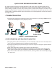
QUICK-START OPERATING INSTRUCTIONS This manual contains detailed operating instructions for all aspects of the DFX flow instrument. The following condensed instructions are provided to assist the operator in getting the instrument started up and running as quickly as possible. This pertains to basic operation of the clamp-on transducer only.
FLOW Top View of Pipe FIGURE 1.2 - TRANSDUCER DIRECTION 3 - TRANSDUCER CONNECTIONS 1) Mount DFX monitor within the length of the transducer cables. While transducer cable extension is not generally recommended, if additional transducer cable length is required, utilize cable and connectors of the correct type and impedance. In many cases, especially if a splice my be exposed to water or other liquids, it may be more effective to replace the entire cable.
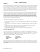
PART 1 - INTRODUCTION GENERAL The DFX ultrasonic flow meter is designed to measure volumetric flow of solids-bearing or aerated liquid within closed conduit. Transducers are available as non-contacting (DT9) or insertion probe (DP7) types. DT9 non-contacting transducers are strapped to the outside of a pipe and are suitable for most installations where the pipe material supports the transmission of ultrasound.
USER SAFETY The DFX employs modular construction and provides electrical safety for the operator. The enclosure is constructed from rugged polycarbonate plastic with UV inhibitors. The enclosure does not contain any conductive materials that can become energized while the door is closed. The keypad is also manufactured from polycarbonate and is designed for outdoor use. The AC power transformer provides 4,000 Volts of isolation from the power supply mains.
PRODUCT MATRIX DDFXD DIGITAL DOPPLER ULTRASONIC FLOW TRANSMITTER DDFXD 2 - A-NN Transmitter Type Options 2) Rate and Totalizer N) None Approvals N) General Safety, CE Approved Power Supply A) 115 VAC B) 230 VAC C) 100 VAC E) 12-28 VDC Totalizer Input/Output 1 N) None 1) 4-20 mA 2) Dual Relay 3) Rate Pulse A) Eight Digit Resettable Input/Output 2 N) None 1) 4-20 mA 2) Dual Relay 3) Rate Pulse DT9 CLAMP-ON DOPPLER TRANSDUCER SET DT9 N Transmitter Type* Approvals 4) Std. Temp/Std. Pipe 5) Std.
DP7 INSERTION DOPPLER PROBE DP7 N Probe Length Approvals 1) 8” (203 mm)* 2) 18” (457 mm) 3) 28” (711 mm) 4) 38” (965 mm) 5) 48” (1220 mm) N) General Safety to US/Canadian standards B) 1½” RF flange, General Safety Consult Factory for Longer Lengths Cable Length Conduit Type Conduit Length 000) 0’ (0m) 020) 20’ (6m) 050) 50’ (15m) 100) 100’ (30m) N) None A) Flexible Armored 000) 0’ (0m) 020) 20’ (6m) 050) 50’ (15m) 100) 100’ (30m) Maximum length : 990’ (300m) in 10’ (3m) increments Maximum len
PART 2 - TRANSDUCER INSTALLATION UNPACKING After unpacking, it is recommended to save the shipping carton and packing materials in case the instrument is stored or re-shipped. Inspect the equipment and carton for damage. If there is evidence of shipping damage, notify the carrier immediately.
Select a transducer mounting location with adequate straight runs of pipe, both upstream and downstream, to achieve stable readings1. Examples of minimum upstream and downstream requirements are included in Figure 2.2. Piping Configuration and Transducer Positioning Flow * 5 14 5 10 5 10 5 10 5 24 5 ** Flow * 24 ** Flow * ** ** Flow * * ** Flow * Downstream Pipe Diameters ** Flow * Upstream Pipe Diameters ** FIGURE 2.
PIPE PREPARATION Before the transducer heads are mounted to the pipe surface, an area slightly larger than the flat surface of the transducer face must be prepared. If pipe insulation is present, it must be peeled back to expose the pipe surface. Typical preparation involves wire brush removal of loose paint, rust, scale or dirt. Paint, if bonded well to the pipe surface, does not need to be removed. The bumps present on ductile iron pipe do not need to be removed.
FLOW Top View of Pipe FIGURE 2.3 - TRANSDUCER PLACEMENT PROCEDURE: 1) Large pipe installations utilize stainless steel straps to secure the transducers to the outside of the pipe. The DFX system is shipped with four 36” (900 mm) straps, which are suitable for pipes up to 39” (1000 mm) diameter. Select the proper number of transducer straps to allow a complete strap to go around the circumference of the pipe.
4) Spread an even layer of coupling compound, approximately 1⁄8” (3 mm) thick, to the flat face of the two transducers. 5) Place each transducer under the strap with the flat face – amber plastic window – positioned towards the pipe. The notch on the back of the transducer will provide a mounting surface for the strap. The transducer cables must be facing in the same direction and downstream of the transducers for proper operation. NOTE: Large pipes may require two people for this procedure.
If the Bronze Hot Tap Kit (p.n. D030-1006-001) or Stainless Steel Hot Tap Kit (p.n. D030-1006-002) accessory kits were ordered with the DP7 probe, a hot tapped installation can be completed. The kits include an isolation valve assembly and are designed for installation in pipes under pressure, up to 700 psi (48 Bar) at 70 °F (21 °C).
PROBE INSERTION Before inserting the DP7 probe into the piping system, it is necessary to calculate the probe insertion depth that will place the measuring electrodes at the proper position in the pipe. In order to complete this calculation, some knowledge of the piping system must be known. Refer to the paragraphs that follow and Figure 2.6 for information regarding this process. The variables required are: t t t t t The overall probe length. Pipe internal diameter (I.D.). Pipe wall thickness.
NOTE: For some low pressure/low temperature applications [less than 30 PSI (2.1 Bar) and less than 100 °F (38 °C)], the probe may be pushed in by hand to decrease the insertion time. To Calculate Insertion Depth Measure and record the following linear dimensions. E C B A = = = = D Probe Length Seal Fitting to Pipe Wall Pipe Wall Thickness 0.
Flow Direction Arrow FIGURE 2.7 - FLOW DIRECTION ARROW PROBE CABLES Before inserting the probe into the pipe, the sensor cables should be routed to the transmitter location. Verify that the supplied cable length is sufficient to meet the installation requirements. While transducer cable extension is not generally recommended, if additional transducer cable length is required, utilize cable and connectors of the correct type and impedance.
CAUTION: Do not run the drive nuts off the rods until the isolation valve is fully closed. 2) After the probe is retracted past the “ball” in the isolation valve, the isolation valve may be closed to isolate the probe from the line and the probe can be removed entirely. CAUTION: If the insertion probe is not above the “ball” of the isolation valve, the valve cannot be closed. If the valve will not close smoothly, the body or tip of the probe is most likely not above the “ball”.
PART 3 - TRANSMITTER INSTALLATION UNPACKING After unpacking, it is recommended to save the shipping carton and packing materials in case the instrument is stored or re-shipped. Inspect the equipment and carton for damage. If there is evidence of shipping damage, notify the carrier immediately. MOUNTING LOCATION The enclosure should be mounted in an area that is convenient for servicing, calibration and for observation of the LCD readout.
4.25" (108.0) 3.93" (99.8) 5.75" (146.1) RUN PROGRAM RELAY 1 RELAY 2 7.00" (177.8) Power Connection Transducer Connection Input/Output Connection (3) ½” (m20) Conduit Holes WALL MOUNT (OPTION) PANEL MOUNT (OPTION) 1.99” (50.5) 0.07”(1.8) Maximum Radius 3.31 (84.1) 6.25” (158.8) 5.19" (131.8) 1.70” (43.2) PANEL CUT-OUT Panel Thickness: 0.5” (12) Max 6.08" (154.4) 6.65" (169.0) FIGURE 3.
TRANSDUCER WIRING CONNECTIONS To access terminal strips for electronic connectors, loosen the two screws in the enclosure door and open the door. 1) Guide the transducer terminations through the transmitter conduit hole located in the bottomcenter of the enclosure. Secure the transducer cable with the supplied conduit nut (See Figure 3.2). JP1 J3 + C3 J4 J2 Transducer Connections FIGURE 3.
JP3 2 1 7 1 3 4 3 VPP12-800 CLASS B 4 6 R VDE ® 9 10 12 JP2 JP1 J3 + C3 J4 J2 Grounding Wire Lock Nut FIGURE 3.3 - TRANSDUCER CONNECTIONS POWER SUPPLY WIRING CONNECTIONS Connect power to the screw terminal block marked J2 in the DFX transmitter. See Figure 3.4 for AC power supplies and Figure 3.5 for DC power supplies. Utilize the conduit hole on the left side of the enclosure for this purpose. Use wiring practices that conform to local and national codes (e.g.
WIRING DIAGRAM CAUTION! To avoid serious injury or damage, disconnect electrical power before servicing this meter JP3 Connections JP3 21 2 1 115 VAC MODULE #2 43 4 3 2 1 2 1 230 VAC JP1 4 3 2 1 JP2 2 1 9-28 VDC 4 3 MODULE #1 J4 JP1/JP2 Connections 115/230 VAC 2 1 J2 2 1 2 1 9-28 VDC 2 AC DC J3 1 Fuse (5x20mm) AC: 0.25 A/250V Delay DC: 1.0 A/250V Delay L1 L2 EARTH +V GND EARTH SYNC SELECT INT EXT RED BLK BLK RED BLU CLR CLR BLU Receive Transmit GND EXT SYNC FIGURE 3.
AC POWER SUPPLY CONNECTIONS DANGER: Line voltages may be present within the enclosure. There is a risk of shock, sparks and death if this product is handled in an unsafe way. Service should only be done by qualified personnel. 1) Verify that the jumpers at JP3 are properly oriented for the power supply. See Figure 3.4. Verify that the jumpers at JP1 and JP2 are not present. 2) Connect L1, L2 and EARTH to the terminals referenced in Figure 3.4. Phase and neutral connections to L1 and L2 are not polarized.
DC POWER SUPPLY CONNECTIONS The DFX may be operated from a 12-28 VDC source, as long as the source is capable of supplying 7 Watts. 12 VDC Supply @ 600 mA minimum 24 VDC Supply @ 300 mA minimum 1) Verify that the jumpers are properly placed. See the wiring diagram located on the inside door of the DFX enclosure or see Figure 3.4. The jumpers at JP3 should not be present and the jumpers at JP1 and JP2 will be in place. 2) Connect the DC power source as illustrated in the schematic in Figure 3.6.
MULTIPLE METER INSTALLATIONS The DFX flow meter contains a provision for synchronizing multiple DFX flow meters together. Synchronization is required when more than one DFX flow meter is mounted on a common pipe or header system. If meters are not synchronized, a phenomena called “cross-talk” can occur between meters, which can lead to erroneous readings or no readings at all. Cross-talk results from the small differences in transmitted frequency generated from two or more different ultrasonic flow meters.
Master Meter Slave Meter WIRING DIAGRAM Slave Meter WIRING DIAGRAM WIRING DIAGRAM CAUTION! To avoid serious injury or damage, CAUTION! To avoid serious injury or damage, CAUTION! To avoid serious injury or damage, disconnect electrical power before servicing this meter disconnect electrical power before servicing this meter disconnect electrical power before servicing this meter JP3 Connections JP3 Connections JP3 21 2 1 2 1 230 VAC JP1 4 3 2 1 2 1 JP1 4 3 2 1 9-28 VDC JP2 J4 JP1/J
WIRING DIAGRAM CAUTION! To avoid serious injury or damage, disconnect electrical power before servicing this meter 4 3 2 1 1 2 1 230 VAC JP1 4 3 2 1 3 MODULE #2 43 4 3 4 JP2 6 2 1 ® VDE I/O: RELAY P.N. D020-1045-102 9 b NO 10 b CM 12 b NC a CM JP2 4 3 MODULE #1 J4 JP1/JP2 Connections 2 R a NO 9-28 VDC 115/230 VAC 7 VPP12-800 CLASS B a NC JP1 J3 J3 1 + I/O: 4-20 mA C3 J2 2 1 2 1 2 P.N. D020-1045-100 Fuse (5x20mm) AC: 0.25 A/250V Delay DC: 1.
INTERNAL POWER CONFIGURATION Ensure that jumpers are in place at JP1 and JP2 on the module – reference Figure 3.10B. In this configuration, the 4-20 mA output is driven from a +24 VDC source located within the DFX flow meter. The 24 VDC source is isolated from DC ground and earth ground connections within the DFX instrument. The module can accommodate loop loads up to 800 Ohms in this configuration.
I/O: 4-20 mA 4-20 mA IN (+) 4-20 mA OUT (-) OUT (-) RTU/PLC MONITOR IN (+) INT PWR JP2 JP1 EXT PWR ISO-MOD P.N. D020-1045-100 Remove Jumpers FIGURE 3.10C - EXTERNALLY POWERED 4-20 mA CONTROL RELAY OUTPUT MODULE Two independent SPDT (single-pole, double-throw, Form C) relays are contained in this module. The relay operations are user configured via the front panel to act in either a flow rate alarm, error alarm or totalizing pulse.
POWER RELAY I/O: RELAY b NO b CM b NC a NO a CM a NC ISO-MOD P.N. D020-1045-102 POWER SOURCE FIGURE 3.11B - EXTERNAL RELAY CONNECTIONS RATE PULSE OUTPUT MODULE The Rate Pulse Output Module is utilized to transmit information to external counters and PID systems via a frequency output that is proportional to system flow rate. The frequency output range of the Rate Pulse Module is 0-2,500 Hz.
500 mVp-p 0 500 mVpp TURBINE IN TURBINE IN I/O: 0-2.5KHz TURBINE - B TURBINE - A OUT (-) IN (+) RTU/PLC MONITOR R +V EXT SENSOR PULSE IN GND RTU/PLC MONITOR ISO-MOD P.N. D020-1045-207 +V 0 TIME +V 0 FIGURE 3.
PART 4 – INSTRUMENT PROGRAMMING GENERAL The DFX is configured through the keypad interface. All entries are saved in non-volatile FLASH memory and will be retained indefinitely in the event of power loss. KEYPAD OPERATION The DFX contains a four-key tactile feedback keypad interface that allows the user to view and change configuration parameters used by the DFX operating system. FIGURE 4.
NUMERIC VALUE ENTRY PROCEDURE NOTE: If you are already in PROGRAM mode and the selection to be viewed or changed is already displayed, proceed to step 3 below. If you are in PROGRAM mode and the selection to be viewed or changed is not displayed, press the UP or DOWN arrow keys and repeat pressing until the desired selection appears. Proceed to step 3. 1) Press MENU. PROGRAM appears in the lower left-hand corner and ID UNITS appears on the lower line of the display.
PIPE INSIDE DIAMETER PIPE ID -- Pipe Inside Diameter Entry (Value) ENGLSH (Inches) METRIC (Millimeters) Enter the pipe inside diameter in inches if INCH was selected as ID UNITS; in millimeters if MM was selected. DISPLAY MODE DISPLAY -- Display Mode Selection (Choice) RATE TOTAL BOTH DIAG To display only the Flow Rate, select RATE. To display only the Flow Total, select TOTAL. To alternately display the Flow Rate and the Total, select BOTH.
ENGINEERING UNITS FOR RATE INTERVAL RATE INT -- Time Interval for Flow Rate (Choice) MIN Minutes HOUR Hours DAY Days SEC Seconds Select a desired engineering unit for flow rate measurements.
FLUID SPECIFIC GRAVITY SP GRAV -- Fluid Specific Gravity (Value) Unitless Value Allows adjustments to be made to the specific gravity (density relative to water) of the liquid. If Pounds (LBS) or Kilograms (KGS) is selected for either the RATE UNT or the TOTL UNT, a specific gravity must be entered for the correct mass flow to be calculated. A list of fluids and their associated specific gravities is located in the Appendix of this manual.
CONFIGURE I/O MODULE 1 CFG MOD1 -- Configure I/O Module 1 (Choice) YES NO This prompt allows access to the setup parameters associated with installation of the optional ISO-MOD interface modules. If NO is selected, the unit will skip ahead to CFG MOD2. If YES is selected, configuration and calibration of the module installed in the first position is accessible.
4-20MA CALIBRATION The 4-20 mA ISO-MOD is factory calibrated and should not require adjustment unless it is replaced. NOTE: The CAL 4MA and CAL 20MA entries should not be used in an attempt to set the 4-20 mA range. Utilize FLOW 4MA and FLOW 20MA, detailed above, for this purpose. CAL 4MA (CHOICE) The 4-20CAL? entry allows fine adjustments to be made to the “zero” and span of the 4-20 mA output. Select YES to access adjustment.
4-20TEST – 4-20 MA OUTPUT TEST Allows a simulated value to be output from the 4-20 mA output. By incriminating this value, the 4-20 mA output will transmit the indicated current value. ISO-MOD RATE PULSE FLOW 0HZ (Value) FL MAXHZ (Value) RATE TST The Rate Pulse Output Module is utilized to transmit information to external counters and PID systems via a frequency output that is proportional to system flow rate.
ISO-MOD DUAL RELAY CONFIGURATION DUAL RELAY RELAY 1 AND RELAY 2 NONE TOTAL FLOW OFF < ON > ERRORS Two independent SPDT (single-pole, double-throw, Form C) relays are contained in this module. The relay operations are user configured via the keypad to act in either a total pulse output, flow rate alarm or error alarm mode. The relays are rated for 200 VAC maximum and a have current rating of 0.5 A resistive load (175 VDC @ 0.25 A resistive).
ERROR ALARM RELAY When a relay is set to ERROR mode, the relay will activate when any error occurs in the flow meter that has caused the meter to stop measuring reliably. See the Appendix of this manual for a list of potential error codes. CONFIGURE I/O MODULE 2 CFG MOD2 – CONFIGURE I/O MODULE 2 The I/O configurations for CFG MOD2 are identical to those detailed in CFG MOD1.
When the unit is powered up, there is a delay before the unit begins transmitting sound into the pipe. During this time, the signal strength is measured and a base signal level is obtained. Typically this is a value of about 20. The unit measures flow by measuring the Doppler frequency shift. The frequency shift is approximately 70 Hz per foot per second. For every foot per second increase in velocity, the signal strength should increase by 1.
GAIN CONTROL GAIN POT – DIGITAL GAIN POT 0-64 Using the arrow keys, increase or decrease the numerical value to set the signal gain level. Typically, optimum flow measurement is made when this value is between 10 and 50. Use the lowest value that provides an accurate and stable flow reading. This adjustment must be made in conjunction with the FILTER setting, and may be an iterative process.
LINEARIZATION LINEAR – ENTRY OF LINEARIZATION DATA The Linearization feature allows for correction of flow readings caused by non-linear flow measurement. This typically occurs when there is insufficient straight piping before or after the location where the transducers are mounted. Up to 10 linearization points may be entered. The microprocessor will perform a linear interpolation between data points entered in the linearization table and apply the associated correction factor to the measured flow rate.
PART 5 - STARTUP AND TROUBLESHOOTING DFX START-UP REQUIREMENTS NOTE: The DFX flow meter system requires a full pipe of flowing liquid before a successful startup evaluation can be completed. Do not attempt to make adjustments or make Manual configuration changes until a full pipe of flowing liquid is verified. NOTE: If an RTV sealant was utilized to couple the transducers to the pipe, the sealant must fully cure before power is applied to the instrument. Most RTVs require 24 hours to cure satisfactorily.
TROUBLESHOOTING Symptom Display does not light up ERROR on the DFX Display Unstable Flow Reading Inaccurate Flow Reading Analog output does not match data collection system 06-DPP-UM-00147 02/12 Resolution 1. Insufficient power to DFX monitor – measure voltage at J2 2. Power supply not properly wired to J2 – See Part 3 3. Fuse F1 is open or not installed 4. Power supply jumpers are not installed properly – See Part 3 5.
Symptom Resolution 1. Verify 0 Hz and MAX Hz flow settings 2. Place oscilloscope or frequency counter on the Rate Pulse module outputs and verify frequency output 3. Run output TEST feature – verify that the Hz output coincides with expected data collection system readings Rate Pulse output does 4. Verify that “K-factor” has been calculated correctly: not match data collection K-factor = Hz/(flow/second) system Example: Max Hz (2,500 Hz) = 10,000 Gallons/Minute K-factor = 2,500 Hz / 166.
APPENDIX SPECIFICATIONS SYSTEM Measuring Principle Doppler Ultrasonic. Velocity Range 0.15 to 30 FPS (0.05 to 9 MPS); minimum calibrated span 0.15 to 5 FPS (0.05 to 2 MPS). Accuracy ±2% full scale, over calibrated span. Liquid Types Liquids containing a minimum of 100 ppm of useful sonic suspended reflectors greater than 35 micron in size, and at least 25% of the overall particle volume is larger than 100 microns. (See Product Applications page for details.
TRANSDUCERS Type Housing Materials Compression mode Ultrasonic; 625 kHz.
06-DPP-UM-00147 02/12 Numeric Entry Specific Gravity SP GRAV X PT 01(÷100) X PT 1 (÷10) X 1 (X1) X 10 (X10) X 100 (X1,00) X 1000 (X1,000) X 10000 (X10,000) X 100000 (X100,000) X 1000000 (X1,000,000) Totalizer Multiplier TOTL MUL GALLONS LITERS MGAL CUBIC FT M CU FT CUBIC ME MEGL TRS ACRE FT OIL BARR (42 Gal) LIQ BARR (31.
FIGURE A-1.2 - MENU MAP -- 2 56 06-DPP-UM-00147 02/12 YES NO 4-20 Calibration? 4-20 CAL? Numeric Entry 20 mA Flow Value FLOW 20MA Numeric Entry 4 mA Flow Value FLOW 4MA Numeric Entry 4-20 mA Output Test 4-20TEST Numeric Entry 20 mA DAC Value 20MA OUT Numeric Entry 4 mA DAC Value 4MA OUT From Module Configuration NONE 4-20 MA RATE RELAY Module Type MOD TYPE To Password n = the relay number 1,2,3,4 1 & 2 would be in module 1. 3 & 4 would be in module 2.
06-DPP-UM-00147 02/12 57 1.315 1.660 1.900 2.375 2.875 3.500 4.000 4.500 5.563 6.625 8.625 10.75 12.75 14.00 16.00 18.00 20.00 24.00 30.00 36.00 42.00 48.00 3.5 4 5 6 8 10 12 14 16 18 20 24 30 36 42 48 Outside Diameter Nominal Pipe Size Inches 1 1.25 1.5 2 2.5 3 12.42 3.834 4.334 5.345 6.407 8.407 10.482 ID 1.185 1.53 1.77 2.245 2.709 3.334 0.165 0.083 0.083 0.109 0.109 0.109 0.134 Wall 0.065 0.065 0.065 0.065 0.083 0.083 SCH 5 29.37 35.37 12.39 13.50 15.50 17.50 19.50 23.50 3.760 4.
06-DPP-UM-00147 02/12 Outside Diameter 1.315 1.660 1.900 2.375 2.875 3.500 4.000 4.500 5.563 6.625 8.625 10.75 12.75 14.00 16.00 18.00 20.00 24.00 30.00 36.00 42.00 48.00 Nominal Pipe Size Inches 1 1.25 1.5 2 2.5 3 3.5 4 5 6 8 10 12 14 16 18 20 24 30 36 42 48 11.626 12.814 14.688 16.564 18.376 22.126 7.813 9.750 ID 0.562 0.593 0.656 0.718 0.812 0.937 0.406 0.500 Wall SCH 60 29.00 35.00 41.00 47.00 11.75 13.00 15.00 17.00 19.00 23.00 3.364 3.826 4.813 5.761 7.625 9.75 ID 0.957 1.
06-DPP-UM-00147 02/12 59 3” 2½” 2” 1½” 1¼” 1” ¾” 5⁄8” ½” I.D. 2.907 0.109 3.125 O. D. Wall 2.435 I.D. 2.625 O. D. 0.095 1.959 Wall 0.083 2.125 O. D. I.D. 1.481 Wall 0.072 1.625 O. D. I.D. 1.245 Wall 0.065 1.375 O. D. I.D. 0.995 I.D. Wail 1.125 0.065 I.D. Wall 0.745 Wall O. D. 0.875 0.065 O. D. 0.652 I.D. 0.750 O. D. 0.049 0.527 I.D. Wall 0.049 0.625 K Wall O. D. Nominal Diameter 2.945 0.090 3.125 2.465 0.080 2.625 1.985 0.070 2.
06-DPP-UM-00147 02/12 16” 14” 12” 10” 8” 6” 4” 3” 4.28 6.90 I.D. O.D. 9.05 6.40 9.05 0.27 8.51 11.10 I.D. O.D. Wall I.D. O.D. 15.30 O.D. 0.34 16.72 I.D. 17.40 Wall O.D. 14.64 12.58 I.D. I.D. 0.31 0.33 13.20 O.D. Wall Wall 13.20 10.32 I.D. 16.66 0.37 17.40 14.58 0.36 15.30 12.52 0.34 10.46 0.39 Wail 0.32 11.10 8.45 0.30 6.34 0.25 Wall 0.28 0.26 4.80 O.D. Wall 3.46 I.D. 3.96 51 0.25 6.90 50 Wall O.D. Size (Inches) 16.60 0.40 17.
06-DPP-UM-00147 02/12 61 20” 18” 16” 14” 12” 10” 8” 6” 4” 3” A 20.26 21.60 O.D. I.D. 18.22 I.D. 0.67 0.64 Wall 19.50 19.50 O.D. Wall 20.00 0.80 21.60 18.00 0.75 16.00 16.20 0.70 17.40 I.D. 17.40 O.D. 13.98 0.60 14.16 I.D. 0.66 15.30 11.96 0.62 13.20 9.96 0.57 11.10 8.03 Wall 0.57 15.30 O.D. Wall 0.54 12.12 I.D. 13.20 O.D. Wall 10.10 11.10 O.D. I.D. 8.13 I.D. 0.50 0.46 Wail 9.05 9.05 O.D. Wall 0.51 6.14 6.02 I.D. 0.48 7.10 4.
LIMITED WARRANTY AND DISCLAIMER DYNASONICS, division of Racine Federated Inc. warrants to the end purchaser, for a period of one year from the date of shipment from the factory, that all new transmitters and transducers manufactured by it are free from defects in materials and workmanship. This warranty does not cover products that have been damaged due to misapplication, abuse, lack of maintenance, or improper installation.
WASTE ELECTRICAL AND ELECTRONIC EQUIPMENT (WEEE) DIRECTIVE In the European Union, this label indicates that this product should not be disposed of with household waste. It should be deposited at an appropriate facility to enable recovery and recycling. For information on how to recycle this product responsibly in your country, please visit: www.racinefed.
RETURN/SALES INFORMATION CONTACTS AND PROCEDURES CUSTOMER SERVICE/APPLICATION ENGINEER: If you have a question regarding order status, placing an order, reviewing applications for future purchases, or wish to purchase a new flow meter, please contact our national sales and marketing headquarters: DYNASONICS Division of Racine Federated Inc.
Division of Racine Federated Inc. 8635 Washington Avenue Racine, WI 53406-3738 Toll-Free in U.S. and Canada Tel: 800-535-3569 Fax: 800-732-8354 Tel: 262-639-6770 Fax: 262-639-2267 www.dynasonics.com DYNASONICS is a registered trademark of Racine Federated Inc. Ultra and Ultralink are trademarks of Racine Federated Inc. Belden is a registered trademark of Belden Technologies, Inc. BACnet is a registered trademark of American Society of Heating, Refrigerating and Air Conditioning Engineers (ASHRAE).