Series 901 Enhanced Ultrasonic Flow Meter Operations & Maintenance Manual REV 4/02
QUICK-START OPERATING INSTRUCTIONS This manual contains detailed operating instructions for all aspects of the D901/M instrument. The following condensed instructions are provided to assist the operator in getting the instrument started up and running as quickly as possible. This pertains to basic operation only. If specific instrument features are to be used or if the installer is unfamiliar with this type of instrument, refer to the appropriate section in the manual for complete details. 1.
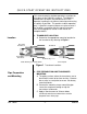
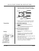
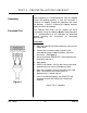
QUICK-START OPERATING INSTRUCTIONS D. Place each transducer under the mounting strap, 180° apart on the pipe. Ensure that the transducer cables are facing the same direction. See Figure 2. Receiving Transducer Transmitting Transducer Figure 2 Transducer E. Route the transducer cable back to the transmitter, avoiding locations near high voltage supply wires. Connections 3. TRANSDUCER CONNECTION A. Do not attempt to add additional cable to the transducers. B.
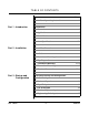
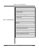
TABLE OF CONTENTS Pages Quick-Start Operating Instructions Part 1 - Introduction Part 2 - Installation 1-2 Introduction General 5 Applications 5 Model Matrix 6 Product Specifications 7-8 Bench Test Procedure 9 Installation Transducer Mounting Locations Pipe Preparation Part 3 - Startup and Configuration Rev.
TABLE OF CONTENTS Pages Instrument Startup and Configuration Part 4 - Troubleshooting CAL.
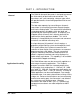
PART 1 - INTRODUCTION General The D901/M ultrasonic flow meter is designed to measure the fluid velocity of liquid within closed conduit. The transducers are a non-contacting, clamp-on type, which will provide benefits of non-fouling operation and ease of installation. The flow meter operates by transmitting an ultrasonic sound from its transmitting transducer through the pipe wall into the flowing liquid.
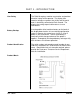
PART 1 - INTRODUCTION User Safety Battery Backup Product Identification The D901/M employs modular construction and provides electrical safety for the operator. The display face contains voltages no greater than 9 Vdc and the metal work is electrically connected to Earth Ground. The display face swings open to allow access to user connections.
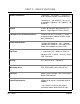
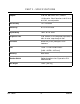
PART 1 - SPECIFICATIONS Ambient Conditions Transmitter - -22 to 160°F [ - 30 to 70 °C], 0-95% relative humidity, non-condensing. Transducers - - 40° to 250°F [ -40° to 121° C] Standard. Optional: - 40° to 400°F [ - 40° to 204°C] Display 2 line x 20 character alphanumeric LCD, back lit. Digit height 0.2 inches [ 5 mm] Transducer to Transmitter Distance Standard: 20 feet [ 6.09 meters ], flexible armored conduit. Optional lengths to 300 feet [ 100 meters ] Power Requirements 115/230 VAC 50/60 Hz ± 10%.
PART 1 - SPECIFICATIONS Outputs 4-20 mA, 600 Ohms max., Isolated. 12 Vdc pulse, 50 mS duration, 0-0.15 Hz to 0-2.5 Hz, user adjustable. Non-linearity ±2 % Full Scale Sensitivity 0.4 % of Full Scale Repeatability ±0.4% of Full Scale Response Time 5-50 seconds, user configured adjustable, to 90% of value, step change in flow. Enclosure NEMA 4X, [IP-65] Fiberglass w/SS hardware. Size 13.5H x 11.3W x 5.
PART 2 - PRE-INSTALLATION CHECKOUT Unpacking Functional Test After unpacking, it is recommended to save the shipping carton and packing materials in case the instrument is stored or re-shipped. Inspect the equipment and carton for damage. If there is evidence of shipping damage, notify the carrier immediately. The D901/M flow meter can be checked for basic functionality using the following Bench Test procedure.
PART 2 - TRANSDUCER INSTALLATION Transducer Mounting Considerations The transducers that are utilized by the D901/M contain piezo electric crystals for transmitting and receiving ultrasonic sound energy through the pipe wall. The transducers can be mounted in three different configurations. The selection of the proper configuration is dependent on the liquid to be measured characteristics.
PART 2 - TRANSDUCER INSTALLATION Table 11 1 Example Upstream Pipe Downstream Diameters Pipe Diameters * ** 1 24 4 2 14 3 3 3 9 3 4 4 8 3 5 8 3 6 24 4 2 5 6 1 The D901/M system will provide repeatable measurements on piping systems that do not meet these requirements, but the accuracy may be influenced to various degrees. CASE 2: Liquid that contains greater than 10,000 PPM [1%] of 30 micron or greater suspended solids or aeration. Top View of Pipe Figure 4 Rev.
PART 2 - TRANSDUCER INSTALLATION The mounting location and straight pipe requirements for CASE 2 liquid characteristics are the same as those describe in CASE 1. The difference will be in the location of the transducers on the pipe. As the discontinuities (suspended solids or aeration) reach a level of approximately 1% or 10,000 PPM, sound can no longer be reliably transmitted through the liquid as it has a tendency to scatter and absorb into the high concentration of Figure 5 discontinuity.
PART 2 - TRANSDUCER INSTALLATION Figure 6 STEP B PIPE SURFACE PREPARATION Before the transducer heads are bonded to the pipe surface, an area slightly larger than the flat surface of the transducer must be cleaned to bare metal on the pipe. (Plastic pipes do not require preparation beyond removal of paint.) Remove all scale, rust and paint. Thoroughly dry and degrease the mounting surfaces.
PART 2 - TRANSDUCER INSTALLATION PROCEDURE: 1. Select the proper number of transducer straps to allow a complete strap to go around the circumference of the pipe. See Table 2 - The straps can be connected together to make a continuous length. Table 2 Pipe Sizes Straps Required 1” to 9” 25 to 225 mm 1 10” to 19” 250 to 480 mm 2 20” to 29” 500 to 740 mm 3 30” to 39” 760 to 1000 mm 4 2. Wrap the strap around the pipe in the area where the transducers are to be mounted.
PART 2 - TRANSDUCER INSTALLATION the same direction for proper operation. See Figure 7. NOTE: Large pipes may require two people for this procedure. 6. Tighten the strap tight enough to hold the transducers in place, but not so tight that all of the couplant squeezes out of the gap between the transducer face and pipe. Ensure that the transducers are squarely aligned on the pipe. Figure 7 7. Route the transducer cable back to the transmitter mounting area avoiding high voltage cable trays and conduits.
PART 2 - TRANSMITTER INSTALLATION Transmitter Installation The enclosure should be mounted in an area that is convenient for servicing, calibration or for observation of the LCD readout. 1. Locate the transmitter within the length of transducer cable that was supplied with the D901/M system. If this is not possible, do not attempt to add additional cable to the transducer. Contact the Dynasonics factory to coordinate an exchange for the proper cable length.
PART 2 - TRANSMITTER INSTALLATION ♦ Where little vibration exist. ♦ Protected from falling corrosive fluids. ♦ Within ambient temperature limits - 22 to 160°F [30 to 70°C] ♦ Out of direct sunlight. A sun and weather shield is available from Dynasonics. P.N. D003-899-001. Direct sunlight may increase temperatures within the transmitter to above maximum limit. 3. Mounting: Refer to Figure 8 for enclosure and mounting dimension details.
PART 2 - ELECTRICAL INSTALLATION Transducer Connections enclosure. Secure the transducer cable with the supplied conduit nut. 2. The terminals on the transducer cable are coded with wire markings. Connect the appropriate wires to the corresponding screw terminals in the transmitter. See Figure 9. NOTE: The transducer cable carries low level signals. Do not attempt to add additional cable to the factory supplied transducer cable.
PART 2 - ELECTRICAL INSTALLATION Optional 0 - 1 mA Output Line Power If the 0-1mA output has been installed on the D901/M, the connections are available on the screw terminal block in the transmitter. Connect a load of not more than 4 K ohms to the terminals. Adjust control R20 [1 mA] to fine tune the output to match the load impedance. Connect line power to the screw terminals marked AC, AC and GND in the transmitter. See Figure 10.
PART 3 - STARTUP AND CONFIGURATION Before Starting the Instrument Instrument Startup Note: The D901/M flow meter system requires a full pipe of liquid before a successful startup can be completed. Do not attempt to make adjustments or change configurations until a full pipe is verified. Note: If Dow 732 RTV was utilized to couple the transducers to the pipe, the adhesive must fully cure before power is applied to the instrument. Dow 732 requires 24 hours to cure satisfactorily.
PART 3 - STARTUP AND CONFIGURATION Keypad Configurations Modes of Operation (covered in the previous sections of this manual) the D901/M can be keypad configured to provide select engineering unit readings of flow and a scaled 4-20mA output. Configuration inputs are made via the keypad and are stored by the microprocessor. The entries are retained by the flow meter’s backup battery in the event of power failure.
PART 3 - STARTUP AND CONFIGURATION Pipe I.D. Input The ID key allows the entry of a pipe’s Internal Diameter. The D901/M utilizes the I.D. constant to process volumetric flow rates such as GPM (Gallons per Minute) or LPM (Liters per Minute). The entry is made as either inches or mm, dependent on whether the unit is configured as U.S. units or Metric units. Press the I.D. key from the ENTRY MODE. The display will show INSIDE DIAMETER This is the present I.D. constant. Enter a new I.D.
PART 3 - STARTUP AND CONFIGURATION Full Scale Input The FULL SCALE key allows the entry of the highest anticipated fluid velocity. The entry is made as either FPS (Feet per Second) or MPS (Meters per Second), dependent on whether the unit is configured as US units or Metric units. The FULL SCALE input is used by the D901/M microprocessor to scale the 4-20mA output and adjust the resolution of the flow rate display. Acceptable input range for the FULL SCALE constant is shown in Table 4. Table 4 I.D.
PART 3 - STARTUP AND CONFIGURATION Totalizer Exponent Input The VOL. PULSE key allows the entry of a totalizer exponent. This feature is useful for accommodating a large accumulated flow. The exponent is a “ X 10 “ multiplier, which can be from 0 (no multiplier) to 2 (X 100). For example, to totalize in GAL X 100, a VOL. PULSE value of 2 would be used (10² or 100). Acceptable input range for the VOL. PULSE constant is shown in Table 5. Table 5 I.D.
PART 3 - STARTUP AND CONFIGURATION When utilizing the MGD engineering UNITS, the totalizer defaults to a VOL. PULSE multiplier of 10E3. This is not reflected on the display. Example: In MGD mode, a VOL. PULSE entry of 3 will result in an effective accumulation of E106 gallons (millions of gallons). Important Note for MGD Configurations The UNITS key allows the selection of measuring units. Table 7 shows applicable codes for the engineering units available. Engineering Units Input Table 7 UNITS CODE U.
PART 3 - STARTUP AND CONFIGURATION By applying a CAL value other than 100%, the factory calibrated readings will be altered by the percentage entered. This CAL value will not be reflected in the 420mA or pulse outputs. For example, if a reading of 175 GPM is displayed and the known flow rate is 160 GPM, a CAL value of X 100 = 91.4% 160 GPM 175 GPM The D901/M will not allow decimal values to be entered as a CAL constant, so round to the nearest whole number. In this case 91%.
PART 3 - STARTUP AND CONFIGURATION Display Damping The DAMP key allows the selection of time duration between display updates. The value selected and entered will result in display updates of n x 2 = seconds between updates Acceptable input ranges for the DAMP constant are shown in Table 9. Table 9 I.D. US METRIC Max 5 5 Min 0.5 0.5 Values outside of this range will result in an OVER! or UNDER! display. Entry of an appropriate value is required. System Damping The TEST Diagnostic Key Rev.
PART 3 - STARTUP AND CONFIGURATION System and Totalizer RESET The RESET key is used for generating a system reset or to reset the accumulated (totalized) flow. Press the RESET button from the ENTER Mode. A choice is then made to : RESET Reset the system VOL. MULT Press VOL PULSE to re-set the totalizer to zero. If the RESET key is pressed again, all configuration constants will return to default values. If the VOL.
PART 4 - TROUBLE SHOOTING CONDITION Unit does not turn “ON” when power is applied POSSIBLE CAUSE • Check AC connections. • Test the fuse • Ensure the terminal block located in the upper left corner of the main PCB is secure • Verify that ribbon cables between PCBs are connected. • Increase the value of the FULL SCALE constant. • Verify that fluid velocity is not greater than 20 FPS [6.08 MPS] • Ensure that the transducers are properly mounted to the pipe.
PART 4 - TROUBLE SHOOTING • If GND connection and pipe are at different potentials, ground D901/M to pipe potential. • If Variable Frequency Drives are being utilized, verify that the D901/M obtains a READ light when the pump turn OFF. If it does, contact the Dynasonics factory. • Increase the DAMP constant from keypad. • Increase the system time constant by turning R17 (DAMP) clockwise till readings are satisfactory.
PART 5 - APPENDICES Appendices Relay Alarm Module Addendum Pipe Dimension Chart: Cast Iron Pipe Dimension Chart: Steel, SS, PVC Velocity to Volumetric Conversion Chart Statement of Warranty Customer Service Rev.
Addendum — Relay Alarm Module General This addendum supplies information not covered in the standard Installation and Operation Manual supplied with the Series D901/D90M Ultrasonic Flowmeter Product. The Series D901/D90M product enclosed in this carton was purchased with an external relay alarm module. The module is enclosed and will need to be mounted seperately from the D901/D90M enclosure.
Addendum — Relay Alarm Module Dead Band and Relay Operation Programming Description: Installation and Operation Manual Addendum Series D901/D90M Alarm Relay Option Origin Date: 7-20-98 Revision: none Revision date: none Page 2 of 2
Ductile Iron Pipe Standard Classes Pipe Outside Size Diameter (inches) (inches) Class 50 Class 51 Class 52 Class 53 Class 54 Class 55 Class 56 ID Wall ID Wall ID Wall ID Wall ID Wall ID Wall ID Wall 0.25 0.26 0.28 0.30 0.32 0.34 3.40 4.22 6.28 8.39 10.40 12.46 0.28 0.29 0.31 0.33 0.35 0.37 3.34 4.16 6.22 8.33 10.34 12.40 0.31 0.32 0.34 0.36 0.38 0.40 3.28 4.10 6.16 8.27 10.28 12.34 0.34 0.35 0.37 0.39 0.41 0.43 3.22 4.04 6.10 8.21 10.22 12.28 0.37 0.38 0.40 0.42 0.44 0.46 3.
Cast Iron Pipe Standard Classes CLASS A Size O.D. (Inches) Inch CLASS B CLASS C CLASS D CLASS E I.D. O.D. Wall Inch Inch I.D. O.D. Wall Inch Inch I.D. O.D. Wall Inch Inch I.D. O.D. Wall Inch Inch CLASS F CLASS G CLASS H I.D. O.D. Wall Inch Inch I.D. O.D. Wall Inch Inch I.D. O.D. Wall Inch Inch I.D. Inch Wall 3 3.80 3.02 0.39 3.96 3.12 0.42 3.96 3.06 0.45 3.96 3.00 0.48 4 4.80 3.96 0.42 5.00 4.10 0.45 5.00 4.04 0.48 5.00 3.96 0.52 6 6.90 6.02 0.44 7.10 6.14 0.48 7.10 6.08 0.
Steel, Stainless Steel, P.V.C. Standard Schedules Nominal OUTSIDE Pipe Size DIAMETER Inches SCH. 5 SCH. 10 (LTWALL) SCH. 20 SCH. 30 ID ID ID Wall ID Wall Wall Wall STD. ID Wall SCH. 40 SCH. 60 ID Wall ID Wall X STG. SCH. 80 SCH. 100 SCH. 120 SCH. 140 SCH. 180 ID ID ID ID Wall 0.815 1.160 1.338 1.687 2.125 2.624 0.250 0.250 0.281 0.344 0.375 0.438 ID Wall ID Wall 1 1.25 1.5 2 2.5 3 1.315 1.660 1.900 2.375 2.875 3.500 1.185 1.530 1.770 2.245 2.709 3.334 0.065 0.
FPS TO GPM CROSS - REFERENCE (Schedule 40) Nominal I.D. Pipe INCH (Inches) 1 1.5 2 2.5 3 3.5 4 4.5 5 5.5 6 6.5 7 7.5 8 8.5 9 1 1.05 2.6989 4.0484 5.3978 6.7473 8.097 9.4462 10.796 12.145 13.490 14.844 16.190 17.540 18.890 20.240 21.590 22.941 24.290 1.25 1.38 4.6620 6.9929 9.3239 11.655 13.99 16.317 18.648 20.979 23.310 25.641 27.970 30.300 32.630 34.960 37.300 39.627 41.958 1.5 1.61 6.3454 9.5182 12.691 15.864 19.04 22.209 25.382 28.555 31.730 34.900 38.070 41.250 44.420 47.
FPS TO GPM CROSS - REFERENCE (Schedule 40) Nominal I.D. Pipe INCH (Inches) 1 1.5 2 2.5 3 3.5 4 4.5 5 5.5 6 6.5 7 7.5 8 8.5 9 18 16.88 697.52 1046.3 1395.0 1743.8 2093.0 2441.3 2790.1 3138.8 3488.0 3836.3 4185.0 4534.0 4883.0 5231.0 5580.0 5928.9 6277.7 20 18.81 866.14 1299.0 1732.0 2165.3 2598.4 3031.5 3464.6 3897.6 4330.7 4763.8 5196.8 5629.9 6063.0 6496.0 6929.1 7362.2 7795.3 24 22.63 1253.7 1880.0 2507.0 3134.1 3761.0 4387.8 5014.6 5641.5 6268.3 6895.1 7522.0 8148.8 8775.6 9402.
Fluid Sound Speeds Original Date: Revision: Revision Date: File: Fluid Acetate, Butyl (n) Acetate, Ethyl Acetate, Methyl Acetate, Propyl Acetone Alcohol Alcohol, Butyl (n) Alcohol, Ethyl Alcohol, Methyl Alcohol, Propyl (I) Alcohol, Propyl (n) Ammonia (35) Anlline (41) Benzene (29,40,41) Benzol, Ethyl Bromine (21) n-Butane (2) Butyrate, Ethyl Carbon dioxide (26) Carbon tetrachloride Chloro-benezene Chloroform (47) Diethyl ether Diethyl Ketone Diethylene glycol Ethanol Ethyl alcohol Ether Ethyl ether Ethyle
Linseed Oil Methanol (40,41) Methyl alcohol (40,44) Methylene chloride (3) Methylethyl Ketone Motor Oil (SAE 20/30) Octane (23) Oil, Castor Oil, Diesel Oil (Lubricating X200) Oil (Olive) Oil (Peanut) Paraffin Oil Pentane Petroleum 1-Propanol (46) Refrigerant 11 (3,4) Refrigerant 12 (3) Refrigerant 14 (14) Refrigerant 21 (3) Refrigerant 22 (3) Refrigerant 113 (3) Refrigerant 114 (3) Refrigerant 115 (3) Refrigerant C318 (3) Silicone (30 cp) Toluene (16,52) Transformer Oil Trichlorethylene 1,1,1-Trichloro-etha
GENERAL TERMS AND CONDITIONS OF SALES 1. PAYMENT – Terms of payment are effective from the actual date of invoice. If, in the Seller’s opinion, the financial condition of the Buyer at any time – or any other circumstances – do not justify the incurrence of production costs of shipment on the terms of payment specified, the Seller may require partial or full payment in advance. Payment terms are net 30 days unless otherwise stated on invoice. 2. F.O.B.
Limited Warranty and Disclaimer Dynasonics, div. of Racine Federated Inc. warrants to the end purchaser, for a period of one year from the date of shipment from our factory, that all new transmitters and transducers manufactured by it are free from defects in materials and workmanship. This warranty does not cover products that have been damaged due to normal use, misapplication, abuse, lack of maintenance, or improper installation.
RETURN OF EQUIPMENT/SALES INFORMATION CONTACTS AND PROCEDURES Customer Service/Application Engineer: If you have a question regarding order status, placing an order, reviewing applications for future purchases, or wish to purchase a new flowmeter, please contact our new National Sales and Marketing Headquarters: DYNASONICS Division of Racine Federated, Inc.
8635 WASHINGTON AVENUE RACINE, WI 53406 TOLL-FREE IN NORTH AMERICA.: TEL: (800) 535-3569 FAX: (800) 732-8354 TEL: (262) 639-6770 FAX: (262) 639-2267 URL: www.dynasonics.