
User manual


5. Equipment installation and Preparation
5.1.
Installation
preparation
Make sure that the E1 line cable matches the equipment model connected to it.
The default effective interface is 75
Ω
BNC. If user wants to use BALANCED
interface, please set the 6
th
group of dip-switches on the bottom.
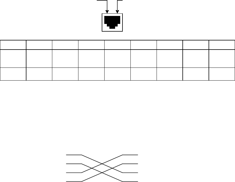
Usage of E1 balanced signal line
Definitions of 120
Ω
balanced interface are as follows:
1
st
pin 8
th
pin
PIN
1 2 3 4 5 6 7 8
Title
TD+
TD-
Not in
use
RD+
RD-
Not in
use
Not in
use
Not in
use
Definition
Output+ Output-
Input+
Input-
When 120
Ω
balanced interface connects with other devices, it is required to make sure of
the pin definition of other devices. The pin connection method of twisted-pair on both ends
is shown as follow:
RC series converter BALANCE-RJ45 E1 transmission device balanced
interface
TD Signal output
TD Signal output
RD Signal input
RD Signal input
Attention: When connecting the twisted-pair, TD and TD should be twisted in pairs, and
so do RD
and RD
.
5.2.
Cautions
when
the
power
is
on
Hot-swapping V.35 interface is forbidden
It is suggested that the protecting ground (middle of the adapter) be connected first
when using DC –48V device. Note that inverse connection of positive and negative
20