
User manual


1
st
bit 2
nd
bit 3
rd
bit 4
th
bit 5
th
bit 6
th
bit 7
th
bit 8
th
bit
Definition Timing
Clock 1
Timing
clock2
TS_FLOW
Time slo
t
follow
BERT
Bit error
test
RX CLK
phase
ALOOP
Local V35
port
loop-back*
DLOOP
Local E1
Line
loop-back*
RLOOP
RemoteE1
Line
loop-back*
ON * * √ √ Negative √ √ √
OFF * * × × Positive × × ×
format*
ON Fractional √ √ √ √ √ √ √
OFF Transparent × × × × × × ×
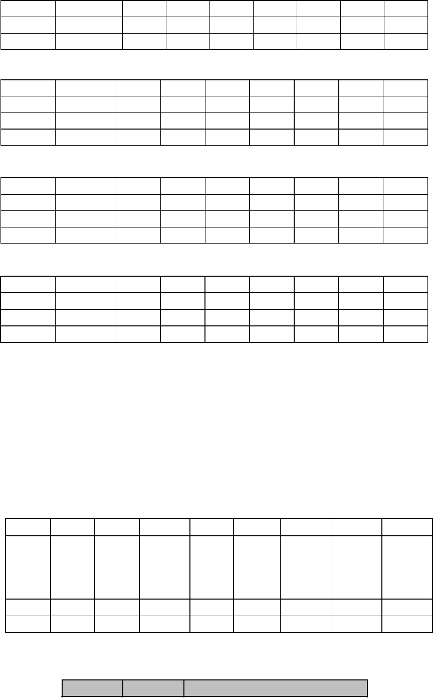
SW2 switch definition (default OFF)
1
st
bit 2
nd
bit 3
rd
bit 4
th
bit 5
th
bit 6
th
bit 7
th
bit 8
th
bit
Definition TS8 TS9 TS10 TS11 TS12 TS13 TS14 TS15
ON √ √ √ √ √ √ √ √
OFF × × × × × × × ×
SW3 switch definition (default OFF)
1
st
bit 2
nd
bit 3
rd
bit 4
th
bit 5
th
bit 6
th
bit 7
th
bit 8
th
bit
Definition TS16* TS17 TS18 TS19 TS20 TS21 TS22 TS23
ON √ √ √ √ √ √ √ √
OFF × × × × × × × ×
SW4 switch definition (default OFF)
1
st
bit 2
nd
bit 3
rd
bit 4
th
bit 5
th
bit 6
th
bit 7
th
bit 8
th
bit
Definition TS24 TS25 TS26 TS27 TS28 TS29 TS30 TS31
ON √ √ √ √ √ √ √ √
OFF × × × × × × × ×
Attention:
If SW1-1 is in the transparent mode, TS1 to TS31 switches are not effective.
If SW1-1 is in the fractional mode, TS1 to TS31 switches are effective and cannot be
all OFF. At least one timeslot is enabled, or else it is not fractional.
If SW3-1(TS16) is enabled, the equipment is working under the PCM31 mode.
If SW3-1(TS16) is disabled, the equipment is working under the PCM30 mode.
Function selecting converter SW5:
The ‘√’ means enable, and ‘×’ means disable.
SW5 converter definition
1. 1
st
and 2
nd
bit: clock selecting switch Timing1, Timing2 (default all ON)
The clock mode is decided by both the 1
st
and 2
nd
switch, the definition is as follow:
1
st
bit 2
nd
bit Clock mode
11