
User manual


Send Data (B) — TD(B) I S
Send Timing (A) — TCK(A) O Y
Send Timing (B) — TCK(B) O AA
Terminal Timing (A) — SCTE(A) I U
Terminal Timing (B) — SCTE(B) I W
Request to Send — RTS I C
Clear to Send — CTS O D
Data Set Ready — DSR O E
Data Carrier Detect — DCD O F
Data Terminal Ready — DTR I H
4.3.
Bottom
Dip
Switches
ON ON DIP
OFF
1
2
3
4
5
6
7
8
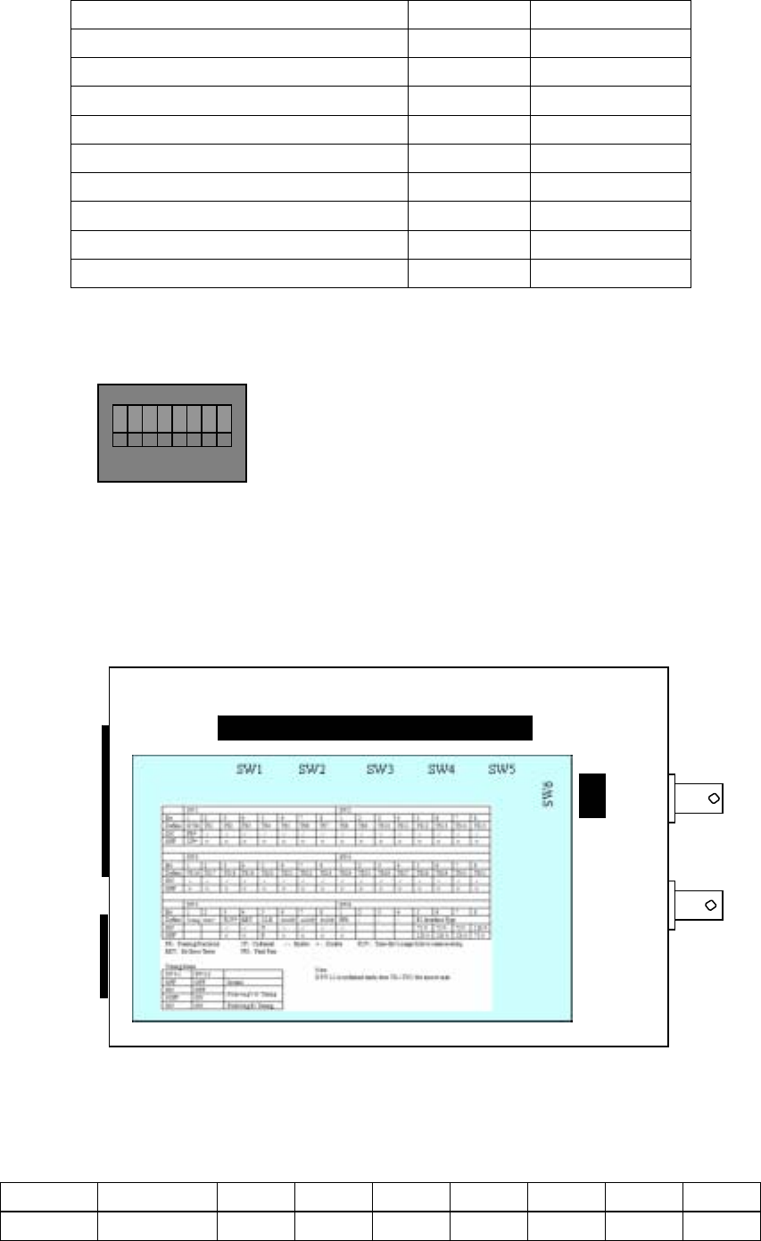
There are 6 groups of 8-bit DIP switches. The positions of the six switches are called
SW1, SW2, SW3, SW4, SW5, and SW6. Every switch is like the above figure. OFF is
below, and ON is above.
There is a DIP switches explanation table on the rear board as follows:
V35
Interface
Power supply
Interface
Timeslot configuration switch SW1 to SW4
The ‘√’ means enable, and ‘×’ means disable.
SW1 switch definition (default OFF)
1
st
bit 2
nd
bit 3
rd
bit 4
th
bit 5
th
bit 6
th
bit 7
th
bit 8
th
bit
Definition Frame TS1 TS2 TS3 TS4 TS5 TS6 TS7
10