RC 903-V35FE1 V.
1. Cautions Warning . Only trained and qualified personnel should be allowed to install, replace or service this equipment. RC903-V35FE1 provides Synchronous Digital Interface complying with the ITU standard. Before power on, the V.35 cable must be well connected. It is strictly forbidden to hot-swap V.35 cable when the converter and the equipment connected by V.35 cable are both power on. RC903-V35FE1 is integrated equipment.
Contents 1. Cautions..................................................................................................................... 1 2. Overview .................................................................................................................... 3 2.1. 2.2. 2.3. 3. 3.1. 3.2. 3.3. 3.4. 3.5. 3.6. 4. 4.1. 4.2. 4.3. 4.4. 4.5. 5. 5.1. 5.2. 5.3. 5.4. Introduction.............................................................................................................
2. Overview 2.1. Introduction RC 903-V35FE1 is an interface converter for V.35 equipment based on E1 network transmission. With the growing utilization of E1 resources, many data transmission solutions using E1 link are accepted by users. RC 903- V35FE1 is standalone equipment, with built-in power supply, and can be placed on the table. It provides signal conversion between V.35 and fractional E1, and can be used in pairs or alone. This equipment will not change the data from V.35 interface. 2.2.
RC903-V35FE1-DC Standalone , one E1 interface ( 75Ω unbalanced or 120Ω Balanced), one standard V35 DCE interface (ISO2593 M34 Female) , -48VDC RC904-V35FE1 Module, one E1 interface(75Ω unbalanced), one standard V35 DCE interface, HDB26 male(transform to ISO2953 M34 female through attached cable) RC904-V35FE1-BL Module, one E1 interface (120Ω balanced, one standard V35 DCE interface) HDB26 male ( transform to ISO2953 M34 female through attached cable) The models in shadow of the above table are include
3. Parameters 3.1. E1 interface: Input impedance: Two 75Ω (unbalanced BNC interface) and one 120Ω (balanced RJ-45 interface) Interface bit rate: 2048Kbps±50ppm Line code: HDB3 Physical characteristics: Complies with ITU-T G.703 Frame structure: Complies with ITU-T G.704 Pass-through characteristics: Complies with ITU-T G.823 Jitter tolerance: Complies with ITU-T G.823 Functions: Completed link alarm indication, Fault Pass Through (FPT) and auto-reset 3.2. V.
3.5. Structure: Standalone Dimensions: 120(W)*39(H)*155(D) mm 3.6.
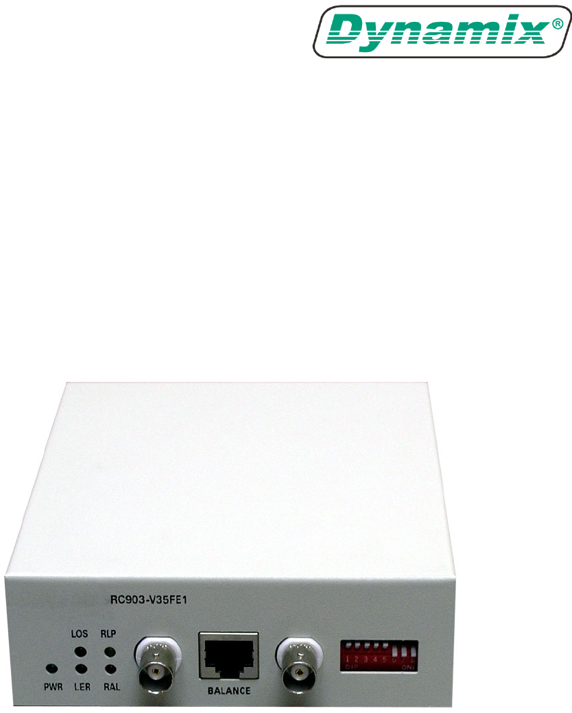
4. User Manual 4.1. Front panel Sketch of the front panel Power Indicator: Power (PWR): On: power is working in good condition Off: Power is off. V35 interface Indicator: TD Green: Flashing: when there is data flow of TD signal (sending data) at the V.35 interface. The Flashing frequency differs with the interface rate of V.35. When it is 64Kbps, the Flashing frequency is the lowest; when it is 2048Kbps, the Flashing rate is the highest. Off: there is no data flow of TD signal at the V.35 interface.
E1 interface alarm Indicator: LOS red: On: loss of receiving signal at local E1; Flashing: loss of receiving signal at remote E1 (only effective at fractional mode); Off: Local and remote signal are normal AIS red: On: Receiving all ‘1’ AIS alarm at the local E1 Flashing: Receiving all ‘1’ AIS alarm at the remote E1 (only effective at fractional mode); Off: Local and remote signal are normal LOF red: On: Receiving Loss of frame LOF alarm at the local E1 (only effective at fractional mode); Flashing: Receivi
4.2. Back panel Sketch of the back panel of AC equipment Sketch of the back panel of DC equipment Power interface: AC interface: standard 3 phase AC power supply interface. Please guarantee that it is correctly grounded. DC interface: DC ports: -48V, PGND, BGND, Please make sure that PGND is grounded; BGND is connected to 0V of DC power supply; -48V is connected to -48V of DC power supply. V.35 interface: The left figure shows V.35 interface ISO 2593 connector.
Send Data (B) — TD(B) I S Send Timing (A) — TCK(A) O Y Send Timing (B) — TCK(B) O AA Terminal Timing (A) — SCTE(A) I U Terminal Timing (B) — SCTE(B) I W Request to Send — RTS I C Clear to Send — CTS O D Data Set Ready — DSR O E Data Carrier Detect — DCD O F Data Terminal Ready — DTR I H 4.3. Bottom Dip Switches ON OFF ON DIP 12345678 There are 6 groups of 8-bit DIP switches. The positions of the six switches are called SW1, SW2, SW3, SW4, SW5, and SW6.
format* ON Fractional √ √ √ √ √ √ √ OFF Transparent × × × × × × × SW2 switch definition (default OFF) 1st bit 2nd bit 3rd bit 4th bit 5th bit 6th bit 7th bit 8th bit Definition TS8 TS9 TS10 TS11 TS12 TS13 TS14 TS15 ON √ √ √ √ √ √ √ √ OFF × × × × × × × × 4th bit 5th bit 6th bit 7th bit 8th bit SW3 switch definition (default OFF) 1st bit 2nd bit 3rd bit Definition TS16* TS17 TS18 TS19 TS20 TS21 TS22 TS23 ON √ √ √ √ √ √ √ √ OFF × × ×
OFF OFF Master clock (internal timing) OFF ON ON OFF V.35 Terminal clock ( followV.35 interface timing ) ON ON Slave clock (followE1 line timing) 2. 3rd bit: selecting switch for auto follow function TS-FLOW (default OFF) 3rd bit Timeslot auto follow function ON Enable OFF Disable To realize the setting of local timeslot bandwidth to follow the remote site, the following pre-conditions must be guaranteed: 1) This equipment is used point to point in pairs.
(2) (3) which means that it has receive the correct test bit. If you choose to set the loop-back of the remote E1 line RLOOP, it means testing the whole process of signal. When testing the local E1 loop-back DLOOP, the bit error test function at the remote equipment and the local E1 loop-back function at the local equipment DLOOP should be on. It means that the test bit sent by the remote equipment loops back on the local equipment.
5.6th 7th and 8th bit: selecting switch of the loop-back type (default OFF) 6th bit 7th bit 8th bit ON Local V35 interface loop-back Local E1 line loop-back Remote E1 line loop-back OFF No loop-back No loop-back No loop-back The loop-back test function is the assistant function for the user to adjust equipment and test the link. The client could set the type of loop-back according to different needs to realize different test functions. (1) Local V.35 interface loop-back test ALOOP DTE or V.
2) There is no PCM equipment occupying Sa bit connecting in series in the E1 link 3) The local and remote equipment should not all be set to the transparent mode. As shown in the above figure, if the above conditioned is fulfilled, the related clock mode and bandwidth could be set. If the connection of E1 is correct, the local LOOP indicator is Flashing, which means that the remote E1 interface loop-back is successful.
5th bit: sending side ‘TX-grounded; 6th bit: receiving side ‘RX-grounded; 7th bit: impedance adjustment at the receiving side 8th bit: impedance adjustment at the sending side Attention: Set according the above table, or else the E1 interface will be abnormal. 4.4. Inside Jump pin definition When the user want to adjust the internal jump pin, please do it under the guidance or agreement of Dynamix technical engineer. Usually it is not necessary; unless it is in sever environment or disturbance.
4.5. Basic Connection The topological figures here are just for reference, users can design it according to practical application. The figures only take RC903-V35FE1 standalone converter as an example. 1) Point-to-point fractional E1 mode in “Master clock — Slave clock” structure (Master clock) (Slave clock) As the above figure shows, when connecting Routers or other equipment with V.35 interface using point-to-point pattern, Routers are required to work at DTE mode.
When using “Master Clock — Slave Clock” connection structure, if DXC and MUX devices are connected in series in E1 link, then DXC, MUX and remote converter should be at Slave Clock Mode (following E1 link clock).
other manufactures. ADM If Routers with E1 interface are used at remote side, users are required to first confirm all the parameters of E1 link, such as fractional/transparent E1, PCM30/31, CRC enable/disable, clock relations, bandwidth distribution and time slot usage etc. If any one of them does not match the setting of the converter, there will be problems in connection. In this case, if devices at both ends work in fractional E1 mode, usually the clock relation is easily ignored.
5. Equipment installation and Preparation 5.1. Installation preparation Make sure that the E1 line cable matches the equipment model connected to it. The default effective interface is 75Ω BNC. If user wants to use BALANCED interface, please set the 6th group of dip-switches on the bottom.
polarity is strictly forbidden. When the equipment is on power and there is no equipment connecting to the V.35 interface, the AIS indicator is on in the transparent mode. This is normal. When the TD and RD indicators is Flashing, it is normal. 5.3. Placement The interface converter should be placed in equipment room, which must be kept clean and air-conditioned.
6. Troubleshooting If there are any problems during installation and operation, please try to solve them according to the following suggestions. If the problems still exist, please contact distributors for help. Power (PWR): indicator OFF Answer: Please check if there is any fault with power supply. Loss-of-Signal (LOS) alarm in E1 link: indicator ON Answer: LOS alarm caution that your E1 interface cannot receive signal. Please check if the input cable is properly connected.
Compatibility with other V.35 Dynamix products Answer: RC903-V35FE1 and RC904-V35FE1 can cooperate with other Dynamix products that have similar functions, such as followings: 1. SUBM-FV35 V.35 module which can be installed in the standalone extendable Multiplexer. 2. RC800-30B-FV35, N x 64K V.35 interface PDH fiber-optic multiplexer, equipped with all the functions of RC903-V35FE1 and RC800-30B single E1 PDH fiber-optic multiplexer. 3.
7. Appendix Explanation of CBL-V35-M34F/M34M-D cable This cable is used to extend v.35 cable. Converter DCE Router DTE CBL-V35-M34F/M34M-D Customer DTE Cable This cable is for the clients who have the need of extending cable. Please specify the length of cable when ordering. The making method is as follow: ISO2593Femal interface M34 Female interface Standard V.
Converter. Converter DCE Node DCE CBL-V35-M34M/M34M-X-D Customer DTE Cable This cable is for the clients who have the need of cross end connection cable. Please specify the length of cable when ordering.