
User manual

5
Chapter 2 Connection Configuration
1. Equipment Interconnection
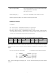
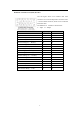
Interconnection of RC series interface converters must follow the rules shown in the table below.
Otherwise, link disconnection or abnormal data transmission may occur.
Central Office Customer Premises
RC903-V35FE1 RC903-V35FE1
RC904-V35FE1 RC903-V35FE1
2. Recommended Basic Connection Type
RC903-V35FE1 converter has 3 types of clock working mode
¾ Master Clock Mode: Using built-in crystal-oscillator clock to be system clock, also
called internal clock
¾ Slave Clock Mode: Using clock provided by E1 receiving link to be system clock, also
called restore clock
¾ Terminal Clock Mode: Using Terminal clock provided by DTE equipment to be system
clock
Choosing the clock mode will be done by setting the dip-switch, see chapter 4 for details.
RC903-V35FE1 is used for point-to-point application. The E1 channel can be provided by PDH
SDH equipment, and also can be set up by connecting cables.
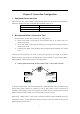
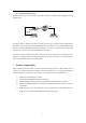
1) Point-to-point fractional E1 mode in “Master clock — Slave clock” structure
As the above figure shows, when connecting Routers or other equipment with V.35 interface using
point-to-point pattern, Routers are required to work at DTE mode. For the convenience of
installation and preparation, users can set Master Clock Mode in local converter and Slave Clock
Mode in remote converter, and the clock source should be in local converter.
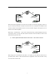
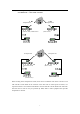
When using “Master Clock — Slave Clock” connection structure, if DXC and MUX devices are
connected in series in E1 link, then DXC, MUX and remote converter should be at Slave Clock
Mode (following E1 link clock).
(Master clock) (Slave clock)