
User manual

4
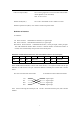
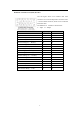
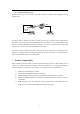
Definition of standard V.35 (DCE) interface:
The left figure shows V.35 interface ISO 2593
connector. Our converter adopts DCE Connector Face
– 34-Pin Female connector, which can be connected
with DTE cable.
The definition of interface is shown below
I — Input O— Output
Pin name Input/Output Pin number
Chassis Ground — CGND - A
Signal Ground — GND - B
Receive Data (A) — RD(A) O R
Receive Data (B) — RD(B) O T
Receive Timing (A) — RCK(A) O V
Receive Timing (B) — RCK(B) O X
Send Data (A) — TD(A) I P
Send Data (B) — TD(B) I S
Send Timing (A) — TCK(A) O Y
Send Timing (B) — TCK(B) O AA
Terminal Timing (A) — SCTE(A) I U
Terminal Timing (B) — SCTE(B) I W
Request to Send — RTS I C
Clear to Send — CTS O D
Data Set Ready — DSR O E
Data Carrier Detect — DCD O F
Data Terminal Ready — DTR I H