
User manual

3
Link error report (LER): ON: receiving signal error occurs at local E1 link (include
AIS at uplink E1, LOF and CRC4)
OFF: no error occurs
Remote alarm (RAL): ON: LOS or LER alarm occurs at remote converter
Remote loop-back test (RLP): ON: remote E1 link in loop-back status
Definition of Interface:
E1 interface:
TX BNC connector 75Ω unbalanced interface, E1 signal output
RX BNC connector 75Ω unbalanced interface, E1 signal input
BALANCE RJ-45 connector 120Ω balanced interface, 1 and 2 pin output; 5 and 6 pin input.
The 75Ω unbalanced interface BNC connector is default interface. If balanced interface is
needed, users need manually set dip-switch on the bottom panel.
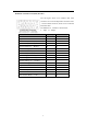
Definitions of 120Ω balanced interface, BALANCE-RJ45 connector for twisted pair
PIN
1 2 3 4 5 6 7 8
Title TD+ TD- Not in use RD+ RD- Not in use
Definition
Output+ Output- Input+ Input-
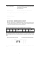
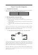
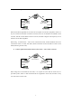
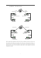
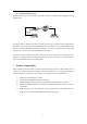
When 120Ω balanced interface connects with other devices, it is required to make sure the pin
definition of other devices. The pin connection method of twisted-pair on both ends is shown
below:
RC series converter BALANCE-RJ45 E1 transmission device balanced interface
TD Signal output
TD Signal output
RD Signal input
RD Signal input
Note: When connecting the twisted-pair, TD and TD should be twisted in pairs, and so do RD
and RD.