
User manual

15
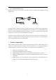
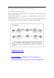
be displayed. Local V.35 interface loop-back test is usually used to check if V.35 cable is properly
connected, or Router port starts working, or the phase relationships of clock and data signals
between the converter and Router is consistent.
As mentioned in previous text, the 6th bit of dip-switch on front panel is defined as bandwidth
active/passive control option when works in normal mode; it is defined as remote/local loop-back
option when doing loop-back test. When the converter is set to local loop-back status, the local
bandwidth will be automatically set to Active Bandwidth Control. In this case, it will not be
affected by the 6th bit of dip-switch on front panel.
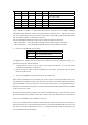
2) The 6th~8th bit of dip-switch: E1 interface type option
75Ω BNC unbalanced interface effective 120Ω RJ-45 balanced interface effective
6th bit 7th bit 8th bit Or 6th bit 7th bit 8th bit
ON ON ON
OFF OFF OFF
Note: The settings above must be strictly followed; otherwise, E1 interface will be abnormal.
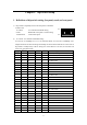
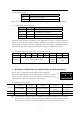
3) The factory default settings on the bottom panel
Dip-switch
position
1st bit 2nd bit 3rd bit 4th bit 5th bit 6th bit 7th bit 8th bit
Status OFF OFF OFF OFF OFF ON ON OFF
Definition
TX CLK
positive
RX CLK
positive
PCM31
CRC
Enable
No
loop-back
75Ω BNC interface
effective