
User manual

14
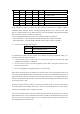
TX CLK positive: sampling TD signal at TCK clock falling edge
TX CLK negative: sampling TD signal at TCK clock rising edge
RX CLK positive: transmitting RD signal at RCK clock falling edge
RX CLK negative: transmitting RD signal at RCK clock rising edge
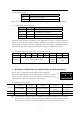
z PCM30/31 option is for that when other equipment (e.g. DXC and MUX) in E1 channel
requires frame structure to be PCM30, then the converter should be set PCM30 effective (N≤
30); when PCM31 is required, the converter should be set PCM31 effective (N≤31). The
settings of this bit of switches must be consistent at both local and remote ends.
z CRC option is used to set “enable” or “disable” CRC function according to requirement of the
channel. The settings of this bit of switched must be consistent at both local and remote ends.
z Loop-back test function is an auxiliary function for users to test equipment and links. When
loop-back function has been set, the loop-back type can be chosen by the 6th bit of dip-switch
on the front panel.
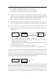
Following conditions have to be met for remote E1 loop-back test:
1. RC903-V35FE1 devices work in pairs as point-to-point connection (or work with other
equipment with N×64K V.35 interfaces)
2. Do not connect in series with PCM equipment (such as DXC and MUX) that engrosses
No.0 time slot in the E1 link
3. Do not set equipment to transparent mode (N=0) on both sides.
4. Only be used on the converters set in “Master Clock Mode” and “Terminal Clock Mode”.
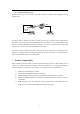
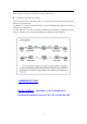
As the above figure shows, after all above conditions satisfied, users can set Master or Terminal
Clock Mode on local converter and set the 5th bit of bottom dip-switch to ON and the 6th bit of
front dip-switch to OFF to process remote E1 loop-back test. If E1 link is in good connection, local
RLP will be lightened, which indicates remote E1 interface loop-back successful. Users can enquire
the status of local Router port, thus the loop-back status will be displayed.
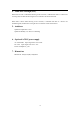
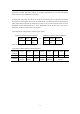
The local V.35 interface loop-back test only takes place on the converters set to “Master Clock
Mode” and “Terminal Clock Mode”. As the above figure shows, users can set Master or Terminal
Clock Mode on local converter and set the 5th bit of bottom dip-switch to ON, the 6th bit of front
dip-switch to OFF and set the first five bits of dip-switch to the bandwidth required to process local
V.35 loop-back test. Users can enquire the status of local Router port, thus the loop-back status will
Local converter
Master clock
Remote converter
Slave clock
DTE or V.35 bi
t
error tester
E1Channel
V.35
Local converter
Master clock
DTE or V.35 bi
t
error tester
E1Channel
V.35