
User manual

12
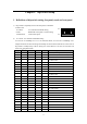
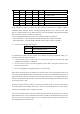
1 1 0 0 1 25×64K=1600K
1 1 0 1 0 26×64K=1664K
1 1 0 1 1 27×64K=1728K
1 1 1 0 0 28×64K=1792K
1 1 1 0 1 29×64K=1856K
1 1 1 1 0 30×64K=1920K(Max. bandwidth 1)
1 1 1 1 1 31×64K=1984K(Max. bandwidth 2)
In the table above, symbol “1” means OFF, and symbol “0” means ON. For example, 384Kbps
bandwidth setting should be “00110”, then the dip-switch should be set to “ON, ON, OFF, OFF,
ON”. It is suggested that you copy down the binary codes corresponding to the desired bandwidth,
then set OFF for symbol “1” and ON for symbol “0”.
Note A: Bandwidth distribution at both local and remote ends must be the same
“Max. Bandwidth 1 ” is the maximum bandwidth allowed under condition of PCM30
“Max. Bandwidth 2 ” is the maximum bandwidth allowed under condition of PCM31
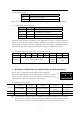
3) 6th bit: V.35 bandwidth control option
6th bit Bandwidth control
OFF Active bandwidth control
ON Passive bandwidth control
To implement the function that the remote device follows local device bandwidth setting, it is
required to follow the instructions below:
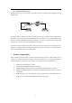
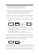
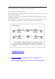
1. RC903-V35FE1 devices work in pairs as point-to-point connection (or work with other
equipment with N×64K V.35 interface)
2. Do not connect in series with PCM equipment (such us DXC MUX) that engrosses No.0
time slot in the E1 link.
3. Do not set equipment to transparent mode (N=0) at both sides.
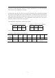
When all the conditions above are satisfied, you can set a device to active bandwidth control at one
side, and passive bandwidth control at the other side. The first 5 bits of bandwidth setting switch at
passive bandwidth control side cannot be set to transparent mode (N=0). It is suggested that all of
them be set to OFF. When the E1 link is connected, the actual bandwidth of passive side is the same
as the setting of active side.
The 6th bit of dip-switch has nothing to do with the clock mode setting, so users can either choose
active bandwidth control at Master clock side, or at Slave clock side. Most users are accustomed to
choose active bandwidth control at Master clock side.
If any one of conditions above cannot be satisfied, then the 6th bit of dip-switches of converters at
both sides must be set to active bandwidth control status, and the actual bandwidth can be set by the
first five bits. Note that especially when N=0, i.e. at transparent mode, the 6th bit should be set to
active bandwidth control at both sides.