
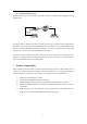
User manual

11
Chapter 4 Dip-switch Setup
1. Definitions of dip-switch setting (frequently used) on front panel
1) Dip-switch is frequently used on the front panel. It should be
set before use.
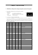
1st~5th bit V.35 interface bandwidth setting
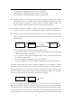
6th bit Bandwidth active/passive control setting
7th and 8th bit Clock mode option
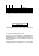
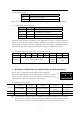
2) 1st ~5th bit: V.35 interface bandwidth setting
V.35 bit rate is N×64Kbps N=1~31 at E1 fractional mode; V.35 bit rate is 2048Kbps at E1
transparent mode. The bit rate setting relationships are shown in the table below. These 5 bits of
dip-switch is actually binary code for setting of N value. When N is set to 0, the converter will
work at E1 transparent mode.
1st bit 2
nd
bit 3rd bit 4th bit 5th bit Bandwidth (bps)
0 0 0 0 0 2048K (E1 transparent mode)
0 0 0 0 1 1×64K=64K (Min. bandwidth)
0 0 0 1 0 2×64K=128K
0 0 0 1 1 3×64K=192K
0 0 1 0 0 4×64K=256K
0 0 1 0 1 5×64K=320K
0 0 1 1 0 6×64K=384K
0 0 1 1 1 7×64K=448K
0 1 0 0 0 8×64K=512K
0 1 0 0 1 9×64K=576K
0 1 0 1 0 10×64K=640K
0 1 0 1 1 11×64K=704K
0 1 1 0 0 12×64K=768K
0 1 1 0 1 13×64K=832K
0 1 1 1 0 14×64K=896K
0 1 1 1 1 15×64K=960K
1 0 0 0 0 16×64K=1024K
1 0 0 0 1 17×64K=1088K
1 0 0 1 0 18×64K=1152K
1 0 0 1 1 19×64K=1216K
1 0 1 0 0 20×64K=1280K
1 0 1 0 1 21×64K=1344K
1 0 1 1 0 22×64K=1408K
1 0 1 1 1 23×64K=1472K
1 1 0 0 0 24×64K=1536K
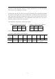
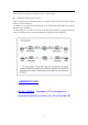
1 2 3 4 5 6 7 8 ON
OF