
User manual

9
Chapter 3 Installation & Preparation
1. Cautions when the power is on
1) Hot-swapping V.35 interface is forbidden
2) It is not advised to hot-swap E1 port
3) When the power is on and E1 transmitting and receiving links are connected, it is safe to
disconnect or connect one of E1 links. It is suggested that the protecting ground (middle of the
adapter) be connected first when using DC –48V device. Note that inverse connection of
positive and negative polarity is strictly forbidden.
2. Placement
1) The interface converter should be placed in equipment room, which must be kept clean and
air-conditioned.
2) Remote converter usually adopts “Slave Clock Mode”.
3) Local converter usually adopts “Master Clock Mode”. In some special cases, it is required to
follow DTE equipment and adopt “Terminal Clock Mode”.
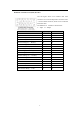
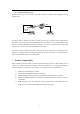
3. Test of connection
z Make sure that no alarm shows on local equipment
z Check if local DTE equipment can process data communication with remote equipment
If the data communication cannot be processed, then test it step by step as follow:
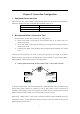
1) Process V.35 port local loop-back test, referring to later part of this manual, introduction to
extended switch setup. If Router indicates success of loop-back test, the V.35 port is proved in
good condition; if Router does not indicate loop-back, first check clock mode, bandwidth
setting of local converter and try to adjust TX CLK and RX CLK phase select switch.
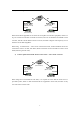
2) After successfully finishing the first step, check if communication in the E1 link works
properly. If converters work in pairs, and No.0 time slot is not blocked in the E1 link, then
remote loop-back test can be processed. If remote E1 port loop-back test is successful, then
local RLP indicator is on, local Router should indicate successful loop-back.
3) If converter does not work in pairs, then it is required to set parameters of E1 interface of other
brand equipment consistent with settings of local converter. Parameters include PCM30/31
format, CRC enable/disable, matching of clock mode etc. After these, please pay attention to
the engrossment of V.35 data in frame structure.
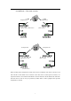
4) After finishing the second step (or make sure the settings of the third step is completely
correct), the communication in the E1 link between local and remote side should be in good
condition. In this case, if remote V.35 interface is connected properly, but it still cannot
communicate properly, please adjust the phase option of TX CLK or RX CLK at remote side.