
User`s manual


NVF-800S 4-Band VDSL IP DSLAM USER’S MANUAL Ver.A.3
Return to the catalogue.
13
LED Indications
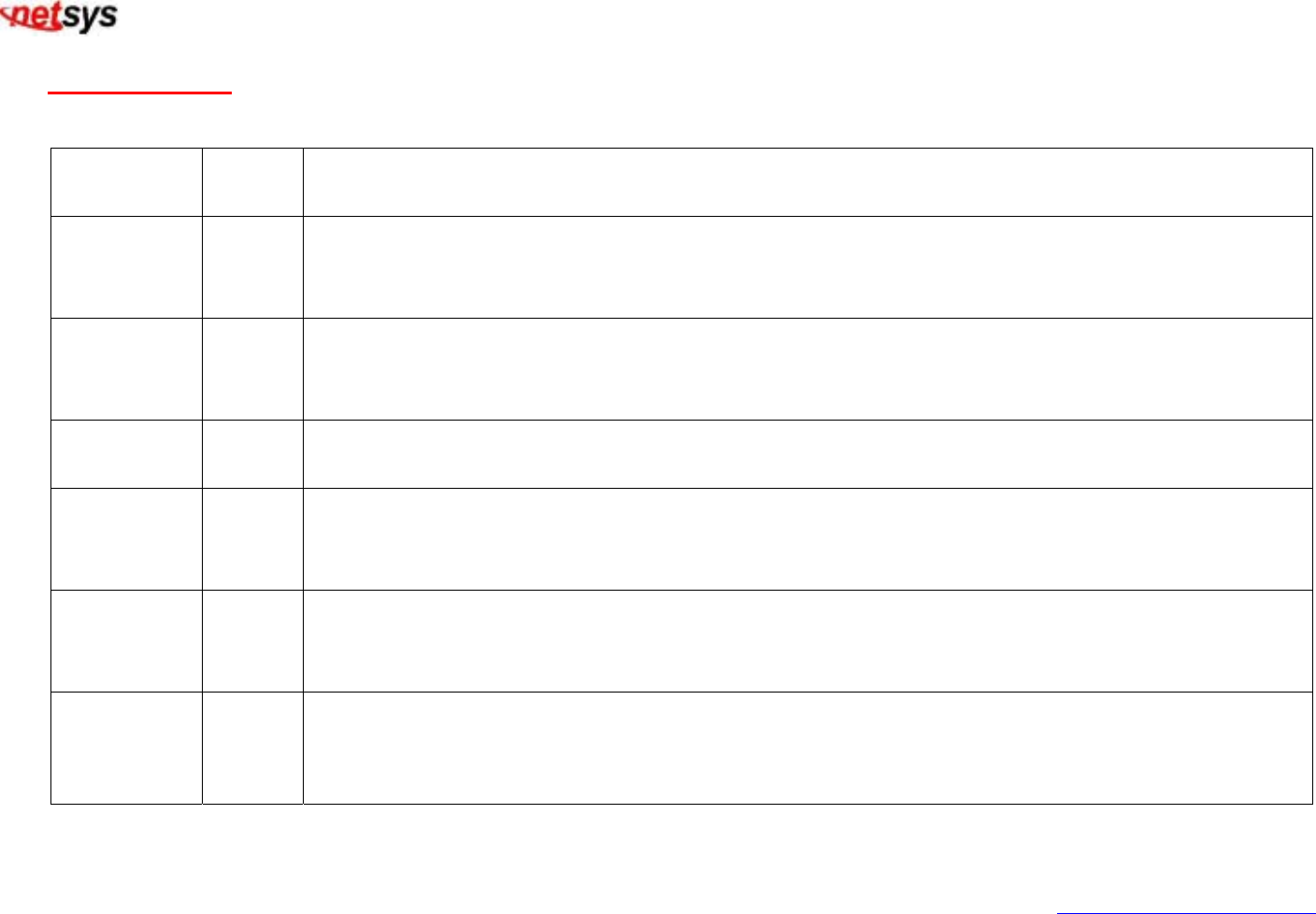
The following describes the function of each LED indicator.
LEDs
Status Descriptions
PWR
(Power LED)
Steady
Green
This LED light is located at the left side on the front panel. It will light up (ON) to show that
the product is receiving power. Conversely, no light (OFF) means the product is not
receiving power.
POST Steady POST(Power On Self Testing)
POST Led will light to show system is booting now.
When system is ready the led will light off.
VDSL Link Steady Each RJ11 station port on the VDSL is assigned an LED light for “Good Linkage”. Each LED
is normally OFF after the power on operation, but will light up steadily to show good linkage.
10
LINK/ACT
Steady
Green
Flashing
Each RJ45 station port on the Ethernet is assigned an LED light for “10M Good Linkage”.
Each LED is normally OFF after the power on operation, but will light up steadily to show
good linkage. And Flashing to show data transmission.
100
LINK/ACT
Steady
Green
Flashing
Each RJ45 station port on the Ethernet is assigned an LED light for “100M Good Linkage”.
Each LED is normally OFF after the power on operation, but will light up steadily to show
good linkage. And Flashing to show data transmission.
1000
LINK/ACT
Steady
Green
Flashing
Each RJ45 station port on the Ethernet is assigned an LED light for “1000M Good Linkage”.
Each LED is normally OFF after the power on operation, but will light up steadily to show
good linkage. And Flashing to show data transmission.