TL3.
REVISION HISTORY Revision 1.0 Date 23.05.
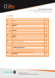
CONTENTS Section 1.0 1.1 2.0 2.1 2.2 2.3 2.4 2.5 2.6 3.0 3.1 3.2 3.3 4.0 5.0 6.0 7.0 7.1 7.2 Page Overview Networks Connections Load Cell LED Switch Antenna Battery Charger Operation Pairing Charging Batteries Technical Specification 4.1 Summary 4.2 Wireless Specification 4.2 Physical Specification 4.
1.0 OVERVIEW The TL-3.0 Telemetry Transmitter is designed for use with strain gauge load cell devices. It communicates wirelessly to the DLM TW-3.0 Telemetry Handheld and any other product within the d+ range. The TL-3.0 operates on a free band 2.4GHz frequency and utilises a bespoke frequency hopping protocol which hops frequency 20 times per second to help reduce interference. The TL-3.0 is “paired” with a receiving device and can be viewed simultaneously on as many receiving devices as required.
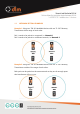
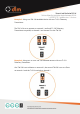
1.1 NETWORK SETTING EXAMPLES Example 1: Using two TW-3.0 Handheld devices with two TL-3.0 Telemetry Transmitters within range of each other. Pair 1 needs to be paired on a network, i.e. Network 1 Pair 2 needs to be paired on a different network, i.e. Network 2 Example 2: Using two TW-3.0 Handheld devices with two TL-3.0 Telemetry Transmitters outside of the range of each other. Both pairs can be paired on the same network as they are far enough apart that interference will not occur.
Example 3: Using one TW-3.0 Handheld device with two TL-3.0 Telemetry Transmitters. The TW-3.0 is set to operate on network 1 and both TL-3.0 Telemetry Transmitters are paired, as channel 1 and channel 2 to the TW-3.0. Example 4: Using two or more TW-3.0 Handheld devices with one TL-3.0 Telemetry Transmitter. One TW-3.0 is set to Master on network 1, the second TW-3.0 is set to a Slave on network 1 and the TL-3.0 is paired on channel 1.
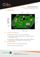
2.0 CONNECTIONS 2.1 LOAD CELL CONNECTION The load cell can be wired as either a 4-wire or 6-wire strain bridge. 1) 6-wire connection – Connect as the picture above. Connections to A and B are not made. Shield is optional. 2) 4-wire connection – Use Signal + and signal -, Sense + and Sense -. Make a link between Excitation + and A, and Excitation - and B. Shield is optional. 2.2 LED CONNECTION Connect the LED anode to LED+ and the LED cathode to LED – The LED should be 2VDC with an internal resistor.
2.3 SWITCH CONNECTION The operation is designed for a push button momentary switch. 2.4 ANTENNA CONNECTION The antenna connection is a U.Fl receptacle and is designed for use with the Molex 47950-0011 antenna and no other antenna may be used 2.5 BATTERY CONNECTION The battery is connected to the TL-3.0 via the 2pin JST connector on a 2.54mm pitch. The part numbers for connectors are: Part Connector Inserts 2.
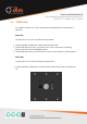
3.0 OPERATION An example of how the TL-3.0 can be housed is shown below with a description of operation. Power On: To power the TL-3.0 on for use follow the steps below: 1. Press and hold the PAIR button until the LED becomes solid 2. The LED will flash once every 3 seconds if the TL-3.0 is connected to a receiving device such as the TW-3.0 Handheld Display. 3. The LED will flash once per second if the TL-3.0 is not connected to a receiving device Power Off: To power the TL-3.
Low Power Mode: When the TL-3.0 is powered but not connected to a receiving device, it will enter a low power mode which will look for signal once every 30 seconds. This is to conserve battery life when the receiving device is powered off, but it is not possible to reach the TL-3.0 to power it off. 3.1 PAIRING The TL-3.0 needs to be paired with a receiving device, in order to establish communication with a new device such as the TW-3.0 Handheld follow the steps below: 1.
3.2 CHARGING If the TL-3.0 is being powered by a battery pack then a suitable 5VDC power source can be connected to the charging connection described in section 2.6. The power source can be supplied from any PC/laptop or any mains to USB charger plug of suitable quality that provides a 5VDC output and 500mA current. WARNING! DO NOT CHARGE BELOW 0°C It is the responsibility of the OEM to ensure the battery being used is suitable for the application and to determine if it can be charged.
3.3 BATTERIES The TL-3.0 allows connection of a multiple battery types which are connected as described in section 2.5. The TL-3.0 is designed to be used with the following battery chemistries: Min Quantity Chemistry Voltage Quantity Chemistry Voltage Quantity Chemistry Voltage Quantity Chemistry Voltage Nominal Max Unit 3.9 V 3.9 V 1.4 V 1.6 V 1 Li-Po 3.4 3.6 1 Li-Ion 3.4 3.6 3 Ni-MH 1.0 1.2 3 Alkaline 1.2 1.
4.0 TECHNICAL SPECIFICATIONS 4.1 SUMMARY Bridge Resistance 350Ω, 700Ω or 1000Ω Battery Battery Life 3.7V Li-Po Rechargeable battery 3.7V Li-Ion Rechargeable battery 3x 1.2V Ni-MH AA/AAA batteries 3x 1.2V Alkaline AA/AAA batteries 700 hours continuous based on a 2Ah battery (2 years storage) Charger USB/5VDC Operating Temperature -20°C to +60°C Frequency 2.4GHz Range Up to 800m line of sight Approvals CE approved and FCC compliant 4.
4.3 PHYSICAL SPECIFICATION Specification 45 x 35 x 10 19 Dimensions Weight 4.4 BATTERY SPECIFICATION Min Quantity Chemistry Voltage Quantity Chemistry Voltage Quantity Chemistry Voltage Quantity Chemistry Voltage Unit Overall L x W x D in mm g Nominal Max Unit 3.9 V 3.9 V 1.4 V 1.6 V 1 Li-Po 3.4 3.6 1 Li-Ion 3.4 3.6 3 Ni-MH 1.0 1.2 3 Alkaline 1.2 1.
5.0 SERVICE AND REPAIR The OEM is responsible for generating suitable service and repair instructions applicable to their application. If there are any issues surrounding firmware operation the unit should be returned to Dynamic Load Monitoring (UK) Ltd for inspection. General points of consideration should be: 1) Prevention of water ingress onto the PCB 2) Prevention of dust ingress onto the PCB 3) Prevention of excessive heat to the batteries or PCB If the TL-3.
6.0 WARRANTY Subject to the terms and conditions set out below, Dynamic Load Monitoring (UK) Ltd (hereinafter 'DLM' or 'the company') warrants its products against defects in materials or workmanship for a period of one year from the date of original purchase. Should a circumstance or condition be observed which might give rise to a claim under this warranty; the user should immediately take the unit out of operation.
7.0 STANDARDS AND APPROVALS 7.1 CE Mark Dynamic Load Monitoring (UK) Ltd tímto prohlašuje, že tento TL-3.0 je ve shodě se základními požadavky a dalšími příslušnými ustanoveními směrnice 2014/53/EU. Undertegnede, Dynamic Load Monitoring (UK) Ltd erklærer herved, at følgende udstyr TL-3.0 overholder de væsentlige krav og øvrige relevante krav i direktiv 2014/53/EU. Hiermit erklärt, Dynamic Load Monitoring (UK) Ltd dass sich das Gerät TL-3.
Hawnhekk, Dynamic Load Monitoring (UK) Ltd, jiddikjara li dan TL-3.0 jikkonforma mal-ħtiġijiet essenzjali u ma provvedimenti oħrajn relevanti li hemm fid-Dirrettiva 2014/53/UE. Alulírott, , Dynamic Load Monitoring (UK) Ltd nyilatkozom, hogy a TL-3.0 megfelel a vonatkozó alapvetõ követelményeknek és az 2014/53/EU irányelv egyéb elõírásainak. Niniejszym Dynamic Load Monitoring (UK) Ltd oświadcza, że TL-3.0 jest zgodny z zasadniczymi wymogami oraz pozostałymi stosownymi postanowieniami Dyrektywy 2014/53/UE.
7.2 FCC This device complies with Part 15.247 of the FCC rules. Operation is subject to the following two conditions: 1) This device must accept any interference and 2) This device must accept any interference received including interference that may cause undesired operation Changes or modifications not expressly approved by Dynamic Load Monitoring Ltd. could void the user’s authority to operate the equipment.