
Specifications


PC BIOS
PP 41x/03x 10-5
10.4 PCI Bus Resource Management
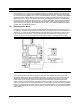
The bus structure of the PP 41x/03x is complex. There are three on-board PCI busses, namely:
• A 32-bit bus which connects the 6300ESB ICH to the SM722 graphics controller.
• A 64-bit bus which connects the 6300ESB ICH to PMC Site 1.
• A 64-bit bus which connects the PEX8114 PCI Express to PCI-X bridge to PMC Site 2 and
the PCI6540 CompactPCI bridge.
The 32-bit bus operates at 33 MHz with 3.3V signaling levels.
The 64-bit bus to PMC Site 1 operates with 3.3V or 5V signaling levels and normally runs at 66
MHz. It may be slowed to 33 MHz if a 33 MHz PMC module is fitted.
The 64-bit bus to PMC Site 2 and the PCI6540 operates with 3.3V signaling levels and normally
runs at 66 MHz. It may be slowed to 33 MHz if a PMC module is fitted. This bus can also operate
at 100 MHz in PCI-X mode by setting some board switches (see Section 2.9.1).
10.4.1 PCI Express Links
The E7520 MCH provides three 8-lane PCI Express links. These links may be configured in several
ways. On this board, they are used to connect various devices as follows:
• An 8-lane (x8) link to the XMC connector on PMC Site 2.
• A 4-lane (x4) link to the PEX8114 PCI Express to PCI-X bridge.
• Single lane (x1) links to each of the three 82573L Ethernet controllers.
The PCI Express links appear as virtual PCI to PCI bridges. The endpoint devices appear as
device 0 on the corresponding virtual PCI bus.
10.4.2 PCI Resource Allocation
The PC BIOS initializes all devices on the local PCI bus, and allocates appropriate memory
address ranges, I/O address ranges, and interrupt routings for all these devices. This process is
automatic as part of the BIOS “Plug-and-play” setup. Devices on the CompactPCI bus may also
have memory, I/O or interrupt resources, these will also be configured by the PC BIOS. The Intel
chipset allows for a flexible allocation of many PCI bus interrupts to the available interrupt inputs on
the PC-compatible interrupt controllers provided on the board. The PC BIOS uses this feature to
program default settings that it considers appropriate for the combination of on-board devices and
any device fitted to the PMC site. In some configurations, depending on the operating system
being used and the capability of the relevant device drivers, it may be necessary for the user to
modify this default configuration, to minimize the sharing of interrupt lines. The PC BIOS Setup
screen for Advanced | PCI Device Configuration allows this.
This screen allows the user to override the PC BIOS default selections for interrupt allocation, but
care must be taken when doing this to avoid conflicts which may result in operating system or even
BIOS “crashes”. To allow maximum flexibility of choice for the user, the PC BIOS performs limited
checks on the user’s interrupt allocation. In the event that there is a problem, it may be necessary
to clear the CMOS memory (see Section 2.6), or even to reset the Extended System Configuration
Data via the Reset Configuration Data field of the BIOS Setup screen for Advanced
configuration settings. The PC BIOS does not allow the user to override the allocation of memory
and I/O address ranges.
WARNING: When reallocating interrupts using the BIOS Setup screens, try to avoid
allocating the PMC interrupts to ones also allocated to other devices. This sharing of
interrupts can cause problems with some operating systems where device drivers do not
correctly handle shared interrupts.