
Specifications

ADDITIONAL LOCAL IO FUNCTIONS
9-12 PP 41x/03x
9.10 IPMI SMIC Interface
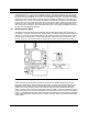
The IPMI sub-system is accessed by the local CPU using the SMIC interface (see Chapter 7 for an
explanation of these terms and of the purpose of IPMI). The following sections outline the register
contents, and example code for using this interface is provided in Section 7.6.
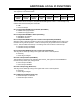
9.10.1 SMIC Data Register
This register is at I/O address 0CA9h. It is dual-ported. Both the CPU and the IPMI microcontroller
can read it or write to it. The SMIC software protocol ensures that no contentions will occur.
7 6 5 4 3 2 1 0
D7 D6 D5 D4 D3 D2 D1 D0
Bits 7-0: SMIC Data Value (Read/Write)
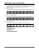
9.10.2 SMIC Control/Status Register
This register is at I/O address 0CAAh. It is dual-ported. Both the CPU and the IPMI microcontroller
can read it or write to it. The SMIC software protocol ensures that no contentions will occur.
7 6 5 4 3 2 1 0
CS7 CS6 CS5 CS4 CS3 CS2 CS1 CS0
Bits 7-0: SMIC Control/Status Value (Read/Write)
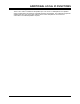
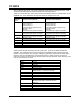
9.10.3 SMIC Flags Register
This register is at I/O address 0CABh. It reports the status of various SMIC flag bits.
7 6 5 4 3 2 1 0
RX_DATA
_RDY
TX_DATA
_RDY
RFU SMI EVT_ATN SMS_ATN RFU BUSY
Bit 0: BUSY (Read/Set)
Bit 1: Reserved
Bit 2: SMS_ATN (Read Only)
Bit 3: EVT_ATN (Read Only)
Bit 4: SMI (Read Only)
Bit 5: Reserved
Bit 6: TX_DATA_RDY (Read Only)
Bit 7: RX_DATA_RDY (Read Only)