
Specifications


ADDITIONAL LOCAL IO FUNCTIONS
9-8 PP 41x/03x
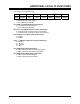
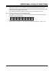
9.6 Interrupt Control Register
This register is at I/O address 215h. It provides control over interrupts from the IPMI.
7 6 5 4 3 2 1 0
ISP
MODE
GPI
INT FLAG
SMS_ATN
INT FLAG
SMIC
NOT BUSY
INT FLAG
RFU GPI
INT ENA
SMS_ATN
INT ENA
SMIC
NOT BUSY
INT ENA
Bit 0: SMIC Not Busy Interrupt Enable (Read/Write)
This bit allows an interrupt to be generated when the IPMI microcontroller clears the SMIC BUSY
flag.
0 = interrupt disabled
1 = interrupt enabled
Bit 1: SMS_ATN Interrupt Enable (Read/Write)
This bit allows an interrupt to be generated when the IPMI microcontroller sets the SMIC
SMS_ATN bit.
0 = interrupt disabled
1 = interrupt enabled
Bit 2: General Purpose Interrupt (GPI) Interrupt Enable (Read/Write)
This bit allows an interrupt to be generated when the IPMI microcontroller sets the GPI INT FLAG
bit.
0 = GPI not enabled
1 = GPI enabled
Bit 3: Reserved
Bit 4: SMIC Not Busy Interrupt Flag (Read/Clear)
0 = event has not occurred
1 = event has occurred
Writing zero to this bit will clear it to zero, writing one will leave it unchanged.
Bit 5: SMS_ATN Interrupt Flag (Read/Clear)
0 = event has not occurred
1 = event has occurred
Writing zero to this bit will clear it to zero, writing one will leave it unchanged.
Bit 6: General Purpose Interrupt (GPI) Interrupt Flag (Read/Clear)
The IPMI microcontroller sets this bit to request an interrupt. If the GPI Interrupt Enable bit is also
set, an interrupt (INT 5) will be generated. Note that if the interrupt is not required, the IPMI
microcontroller can use this bit to signal status to the processor.
0 = no interrupt request
1 = interrupt request
Writing zero to this bit will clear it to zero, writing one will leave it unchanged.
Bit 7: Microcontroller Firmware Mode (Read Only)
This bit indicates the operating mode of the IPMI microcontroller. See Section 7.7 for further details
of In System Programming (ISP).
0 = normal operation (i.e. IPMI BMC or SMC)
1 = ISP