
Specifications


ADDITIONAL LOCAL IO FUNCTIONS
PP 41x/03x 9-7
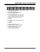
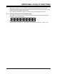
9.5 CPCI Status Register
This register is at I/O address 214h.
7 6 5 4 3 2 1 0
RFU FAL# DEG# CPCI
V(I/O)
OK
CPCI BUS
SPEED
FORCE
SATELLITE
PCI
PRESENT
SYSEN#
Bit 0: CompactPCI SYSEN# Pin Status (Read Only)
This bit indicates whether or not the board is plugged into the System Controller slot.
0 = not System Controller
1 = System Controller
Bit 1: CompactPCI PCI_PRESENT# Pin Status (Read Only)
This bit indicates whether or not the PCI bus is present at this backplane slot.
0 = PCI bus not present
1 = PCI bus present
Bit 2: Force Satellite Mode (Read Only)
This bit indicates the state of the Satellite Mode switch (see Section 2.10). This switch is used to
force Satellite Mode irrespective of which backplane slot the board is plugged into.
0 = Normal Mode selection
1 = Force Satellite Mode
Bit 3: CompactPCI Bus Frequency (Read Only)
0 = 33 MHz
1 = 66 MHz
Bit 4: CompactPCI V(I/O) Voltage Status (Read Only)
0 = voltage not OK
1 = voltage OK
This bit reports the status of the CompactPCI bus V(I/O) voltage. It reads 1 if the V(I/O) voltage at
the backplane is greater than 3V.
Bit 5: CompactPCI ‘DEG#’ Signal is the cause of NMI (Read Only)
0 = event has not occurred
1 = event has occurred
Bit 6: CompactPCI ‘FAL#’ Signal is the cause of NMI (Read Only)
0 = event has not occurred
1 = event has occurred
NOTE: DEG# & FAL# only generate an NMI when first asserted. They will not generate
another interrupt until they have cycled false then true again. Bits 5 and 6 can be used as
monitoring bits for these signals as they may be asserted for some time. The clearing of
these bits is PSU dependant and beyond the scope of this document.
Bit 7: Reserved