
Specifications


ADDITIONAL LOCAL IO FUNCTIONS
9-6 PP 41x/03x
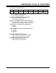
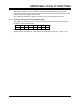
9.4 General Purpose I/O Register
This register is at I/O address 213h.
7 6 5 4 3 2 1 0
EXT
RESET
FAN
SENSOR
INPUT 1 INPUT 0 RFU USB
POWER
OUTPUT 1 OUTPUT 0
Bits 1 - 0: General Purpose Outputs to Transition Module (Read/Write)
0 = set output line to 0
1 = set output line to 1
Bit 2: Transition Module USB Power Enable (Read Only)
0 = RTM USB power is Off
1 = RTM USB power is On
Bit 3: Reserved
Bits 5 - 4: General Purpose Inputs from Transition Module (Read Only)
0 = input line is at 0
1 = input line is at 1
Bit 6: Fan Sensor Status from Transition Module (Read Only)
0 = input line is at 0
1 = input line is at 1
Bit 7: Ext Reset Status from Transition Module (Read Only)
0 = input line is at 0
1 = input line is at 1
NOTE: A multiplexed serial I/O scheme is used to connect these register bits to the I/O
pins on the Transition Module. Because of this, there is an output latency of 80µs and the
maximum input frequency (to avoid losing input transitions) is approximately 6.2 kHz.