
Specifications


ADDITIONAL LOCAL IO FUNCTIONS
9-4 PP 41x/03x
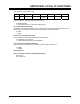
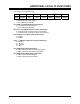
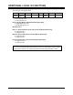
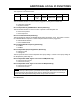
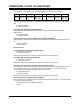
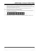
9.2 Status & Control Register 1
This register is at I/O address 211h.
7 6 5 4 3 2 1 0
FP NMI IPMI
NMI
DEG &
FAL NMI
MASK
GPE#
STATUS
GPE#
SMI
ENABLE
PME#
STATUS
PME# SMI
ENABLE
USER LED
Bit 0: User LED (Read/Write)
0 = User LED Off
1 = User LED On
NOTE: The User LED may be configured to light when the CPU reaches its maximum
specified operating temperature (see Section 11.2.3). In this configuration, writing to this
bit will not affect the User LED.
Bit 1: MCH PME# SMI Enable (Read/Write)
This bit allows a System Management Interrupt (SMI) to be generated when the E7520 MCH
Power Management Event (PME#) output is asserted.
0 = SMI disabled
1 = SMI enabled
Bit 2: MCH PME# Status (Read Only)
This bit indicates the status of the E7520 Power Management Event (PME#) output.
0 = PME# output is not asserted
1 = PME# output is asserted
Bit 3: MCH GPE# SMI Enable (Read/Write)
This bit allows an SMI to be generated when the E7520 MCH General Purpose Event (GPE#)
output is asserted.
0 = SMI disabled
1 = SMI enabled
Bit 4: MCH GPE# Status (Read Only)
This bit indicates the status of the E7520 General Purpose Event (GPE#) output.
0 = GPE# output is not asserted
1 = GPE# output is asserted
Bit 5: DEG# and FAL# Mask (Read/Write)
This bit allows the interrupt from the CompactPCI DEG# and FAL# signals to be masked (i.e.
disabled).
0 = enable interrupt
1 = mask interrupt (power-on default)
Bit 6: IPMI is the cause of NMI (Read/Clear)
0 = event has not occurred
1 = event has occurred
Writing zero to this bit will clear it to zero, writing one will leave it unchanged.
Bit 7: Front Panel Switch is the cause of NMI (Read/Clear)
0 = event has not occurred
1 = event has occurred
Writing zero to this bit will clear it to zero, writing one will leave it unchanged