
Specifications

ADDITIONAL LOCAL IO FUNCTIONS
PP 41x/03x 9-3
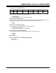
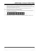
9.1 Status & Control Register 0
This register is at I/O address 210h.
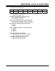
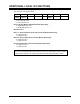
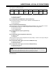
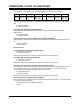
7 6 5 4 3 2 1 0
REV2 REV1 REV0 RFU CONSOLE
PORT
CONSOLE USER MODE
Bit 0: Mode Switch (Read Only)
Used to define the operating mode following a reset.
0 = BIOS operation
1 = CPSA operation Bit 1: User Switch (Read Only)
Bit 1: User Switch (Read Only)
Available for user defined purposes when the board starts up in BIOS mode (see Section 10.1). In
CPSA (factory test) mode this switch selects between MTH and Soak operation.
0 = MTH
1 = Soak
Bit 2: Console Switch (Read Only)
Used to define the BIOS default standard input/output mode.
0 = input/output via serial port
1 = input via keyboard/output via VGA adapter
Bit 3: Console Port Switch (Read Only)
This bit indicates the setting of the Console Port Switch (see Section 6.1.2).
0 = COM1
1 = COM2
Bit 4: Reserved
Bits 7- 5: Hardware Revision Strapping (Read Only)
000 = Rev A,
001 = Rev B etc…