
Specifications


INTELLIGENT PLATFORM MANAGEMENT INTERFACE
PP 41x/03x 7-3
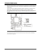
7.3 IPMI Overview
The PP 41x/03x board includes hardware and firmware that implements an IPMI as a separate
resource to the main Intel Pentium M processor. The processor communicates with the IPMI
subsystem through a standardized hardware interface using multi-byte message sequences,
transferring one byte at a time using a handshaking protocol. Instructions can be sent to the IPMI
subsystem with a command and response message pair. The IPMI subsystem may in turn
communicate with additional hardware in the chassis using similar message sequences transferred
over two Intelligent Platform Management Busses (IPMB). The IPMB 0 and IPMB 1 busses each
provide a 2-wire interface based on the Philips® I2C protocol, and in the CompactPCI chassis
connects to all boards on the CompactPCI backplane via the J1 and J2 connectors.
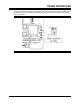
The IPMB 0 bus and IPMB 1 bus can connect to additional intelligent or non-intelligent devices
which may act as sensors or simply data sources and sinks. These devices may include fan or
power supply monitoring hardware, temperature sensors or perhaps just non-volatile memory. The
IPMI specifications define data structures for these sensors that are stored in non-volatile memory,
and describe both control and run-time status (event) information that can be retrieved by System
Management Software.
As the IPMI subsystem on the PP 41x/03x board is separated from the main processor, many of its
features can operate when main power is removed, provided that power is supplied to the board
through the IPMB_PWR pin of the J1 connector. This allows the board to be interrogated via the
IPMB 0 bus even in a power-down state, which may be useful when the board is operating in
Satellite mode.
The programming interface to the IPMI subsystem is via the System Management Interface
Controller (SMIC). This is a set of I/O registers accessed using a polled handshaking protocol.
Example software for driving this interface is provided in Section 7.6.1. When the board is acting
as an SMC, software running on the local processor may only access local IPMI resources through
the SMIC interface. When the board is acting as the BMC, software running on the local processor
may access both on-board IPMI resources and those elsewhere on the IPMB.
The implementation of IPMI on this board provides the following functions.
7.3.1 Message Passing
The flow of information in an IPMI compliant system is achieved by using messages. A transaction
consists of a request and a response message pair. The interface between the System
Management Software and the Baseboard Management Controller uses simple messages which
contain enough information to allow a response to be generated. The “Get Message” and “Send
Message” commands are used to pass information to the IPMB and embed simple messages with
channel routing information.
7.3.2 Events
Events can be generated whenever a system failure is detected. These events are stored in the
System Event Log and can be retrieved by the System Management Software that can process the
events and determine what, if any, corrective action can be taken.
7.3.3 System Event Log
Events are stored in the System Event Log which is held in non-volatile memory. The System
Management Software can access the System Event Log and by analyzing the events may be able
to determine the sequence of events that caused the system failure.