
Specifications

PP 41x/03x 5-1
5 ETHERNET INTERFACES
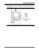
The PP 41x/03x board is fitted with three independent 1 Gigabit Ethernet interfaces, implemented
with three Intel 82573L controllers. One of these devices provides the front panel Ethernet
interface, the other two provide the rear Ethernet interfaces.
The rear Ethernet interfaces can connect in different ways, depending primarily on the build
configuration of the board. This configuration is indicated by the first digit of the board name suffix;
refer to the data sheet for details.
By convention, in this manual the front panel Ethernet interface is numbered as 0 and the rear
Ethernet interfaces are numbered as 1 and 2. Operating system drivers may renumber these
devices to conform to their driver conventions.
It is possible to boot-load the board through the Ethernet interfaces by setting appropriate BIOS
configuration options. See Section 10.3 for more details.
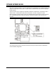
5.1 Rear Ethernet Configuration
If the board is built for operation with Rear Ethernet, both of the rear 82573L interfaces connect via
J3 to a Transition Module that provides the isolating “magnetics” to support standard RJ45
connectors and Category 5 cable.
5.2 PICMG 2.16 Configuration
If the board is built for operation with backplane networking (PICMG 2.16), both of the rear 82573L
interfaces connect via J3, but the isolating “magnetics” are now also built into the PP 41x/03x board
itself. This allows the board to connect directly to fabric boards via the J3 sub-plane of a PICMG
2.16 backplane. If a Transition Module is used, it must be wired or jumpered such that it does not
connect to the pins on J3, which provide the Ethernet signals. The AD PP5/001-4xU,
AD PP5/002-0x and AD PP5/003-0x Transition Modules are fitted with switches to provide this
isolation where necessary.
5.3 Ethernet Interface Identification
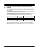
Table 5-1 describes how the three Ethernet interfaces are numbered on the front panels, by the
BIOS and by various operating systems. In a PICMG 2.16 environment, Ethernet Interface Rear A
corresponds to Link Port A and Ethernet Interface Rear B corresponds to Link Port B.
Front Panels Interface
PP 410/03x AD PP5/001 AD PP5/002
BIOS Windows Linux
Front Eth 0 Front Connection 3 Eth 1
Rear A Eth 0 Eth 2 Rear A Connection 1 Eth 0
Rear B Eth 1 Eth 3 Rear B Connection 2 Eth 2
Table 5-1 Ethernet Interface Identification