
Specifications

HARDWARE INSTALLATION
PP 41x/03x 2-21
2.12.1 Non Hot Swap Procedure - Installing
The board is installed and powered up as follows:
a) Make sure that system power is turned OFF.
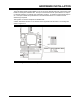
b) Slide the board into the designated slot, making sure that the board fits neatly into the
runners.
c) Push the board into the card-cage until the J1 ... J5 connectors are firmly located. Use the
injector/ejector handles for the final push.
d) Screw the ejector handle retaining bolts into the holes in the chassis.
e) Connect the I/O cables to the connectors on the board’s front panel and fix in place with the
connectors’ retaining screws.
f) If using a Transition Module, install it at the rear of the backplane and connect the I/O
cables.
g) Power-up the system. The following sequence of events should then occur:
• The green “RUN” LED and the yellow “POST” LED on the front panel will light.
• The yellow “POST” LED will switch OFF.
If power-up does not follow the sequence described above this will indicate that the board is not
operational.
NOTE: This sequence of events assumes the PP 41x/03x board has Concurrent
Technologies standard BIOS firmware and that the board is configured to the factory
setting described in Section 2.3.
2.12.2 Non Hot Swap Procedure - Removing
To remove the board, shut down the application and operating system software before powering
down the system, opening the ejector handles and extracting the board.
2.12.3 Hot Swap Procedure - Installing
The board is installed and powered up as follows:
a) Slide the board into the designated slot, making sure that the board fits neatly into the
runners.
b) Push the board into the card-cage until the J1 ... J5 connectors are firmly located. Use the
injector/ejector handles for the final push.
c) The following sequence of events should then occur:
• The blue “Hot Swap” LED will flash once.
• The green “RUN” LED and the yellow “POST” LED on the front panel will light.
• The yellow “POST” LED will switch OFF.
If power-up does not follow the sequence described above this will indicate that the board is not
operational.
a) Screw the ejector handle retaining bolts into the holes in the chassis
b) Connect the I/O cables to the connectors on the board’s front panel and fix in place with the
connectors’ retaining screws.
c) If using a Transition Module, install it at the rear of the backplane and connect the I/O
cables.