
Specifications

HARDWARE INSTALLATION
2-20 PP 41x/03x
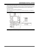
2.12 Installation and Power-up
Before the board is installed in a CompactPCI chassis, check the following points:
• The backplane V(I/O) configuration. The PP 41x/03x board supports either 5V or 3.3V V(I/O)
automatically. Some CompactPCI backplanes are pre-wired for a particular voltage and others
can be configured by the user. For 66 MHz CompactPCI operation the voltage must be 3.3V.
WARNING: V(I/O) must be wired on the backplane. If it is not wired the board will lock up
during POST.
• The Power Supply Unit current capabilities. The board draws current primarily from the +5V
and 3.3V rails, and the details are provided in Section A.4.
• Front panel keys. PICMG 2.10 describes a method of keying CompactPCI board front panels
to individual chassis slots. Keying pins for this purpose are supplied with the board but are not
fitted. The user is referred to PICMG 2.10 for information on using these keys.
• Rear Transition Module Configuration. The AD PP5/001-4xU, AD PP5/002-0x and
AD PP5/003-0x Rear Transition Modules are intended for use with the PP 41x/03x board, and
have switch options to configure them for rear panel Ethernet or PICMG 2.16. Refer to the
appropriate Transition Module’s Technical Reference manual for further details.
The board can be installed as a System Controller in the System slot or as a Peripheral or Satellite
board in a Peripheral slot. In Satellite mode the CompactPCI interface is disabled and hence the
board will not be recognized by the System Controller. When acting as the System Controller, the
board cannot be Hot Swapped.