
Specifications

HARDWARE INSTALLATION
2-10 PP 41x/03x
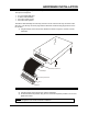
2.7.2 CompactFlash Storage Kit (AD 200/001)
The option kit comprises:
• A CompactFlash carrier module with attached ribbon cable
• Four M3 panhead screws
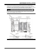
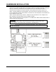
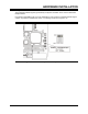
CompactFlash Carrier Module
CompactFlash Sites
Site 1
Site 2
Pillars
P5 Connector
Figure 2-8 CompactFlash Carrier Module Installation
To install the CompactFlash carrier module, follow these instructions:
1) The M3 panhead screws may be loosely screwed into the end of the pillars, if so unscrew
them.
NOTE: Do not unscrew the countersunk screws attaching the pillars to the circuit board.
2) Fix the module into position using the four panhead screws referred to earlier. Do not
over tighten the screws.
NOTE: If the board is likely to be subjected to mechanical vibration a suitable thread lock
compound applied to the screws should be considered.
3) Connect the captive ribbon cable connector to P5 on the PP 41x/03x board.
The CompactFlash sites are labeled CompactFlash 1 and CompactFlash 2.
If a single CompactFlash card is fitted, it should always be installed into site 1. Site 2 should be
used only when two CompactFlash cards are fitted.
The CompactFlash card(s) may be retained in position by fitting short M3 screws and spacers into
the holes near the long edge of the carrier. This will protect against accidental removal due to
vibration or deliberate but unauthorized removal.
NOTE: If more than one CompactFlash module is fitted, the module in the CompactFlash
2 site must support operation as a Slave device.
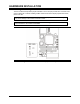
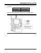
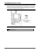
The DIL switch on the AD 200/001 should be set as shown in Figure 2-9.
ON OFF
4
3
2
1
Figure 2-9 AD 200/001 DIL Switch Settings