
Specifications

HARDWARE INSTALLATION
PP 41x/03x 2-7
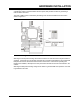
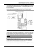
2.6 Battery Installation/Replacement
The on-board Real-Time Clock and CMOS memory used by the PC BIOS firmware are powered by
a 3.3V Lithium battery when the board is powered OFF. It is advisable, for the battery to be fitted
prior to using the board. Figure 2-5 shows how to do this. One battery is supplied with the board,
but it is not normally fitted.
If the board is operated without a battery, the User Selectable NVRAM Defaults feature can be
used to override the factory default NVRAM settings. See Section 10.5 for further details.
Figure 2-5 Battery Fitting and CMOS Clear Jumper
The battery should be replaced when the voltage falls below 2.8V. Depending on the way in which
the board is operated and stored, battery life should be in excess of 5 years. The life expectancy
will fall if the battery is subjected to long periods at temperatures of 45°C or above. It will also fall if
the battery is fitted to a board that is stored in its conductive bag even at room temperature.
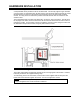
CAUTION: When replacing the battery, proper anti-static precautions must be observed.
WARNING: Dispose of battery properly. DO NOT BURN. The date and time settings will
need to be initialized if the battery is disconnected.
If the BIOS setup screens have been used to set up the board for an invalid configuration, or in
other fault conditions, it may be useful to be able to reset the contents of the CMOS RAM and
Real-Time Clock. In this case, the CMOS Clear Jumper can be used.
To clear the CMOS RAM to a known state, fit the CMOS Clear jumper and apply power. When the
board is next powered down remove the jumper, otherwise CMOS RAM will again be reset.