
Specifications
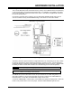

HARDWARE INSTALLATION
2-6 PP 41x/03x
2.5 On-board CompactFlash Site
A CompactFlash site is provided on the PP 41x/03x board. The site fully supports Type I modules.
A Type II module or a MicroDrive may be fitted, but the user should be aware that these are 5.0mm
tall and therefore encroach into the clearance zone between the PP 41x/03x board and PMC
module. This may cause an interference problem if the PMC module also encroaches into this
clearance zone.
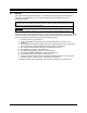
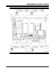
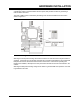
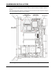
The CompactFlash site is located under PMC site 1 as shown in Figure 2-4 below. The site faces
the top edge of the board, hence the board must be removed from the chassis in order to insert or
remove the module. To fit a module, orient it such that the connector end is facing the socket and
the label side is away from the board, and gently slide it into the socket.
Figure 2-4 CompactFlash Site
The module will normally be adequately retained by the card edge guide of the chassis. However,
holes are provided for the supplied retaining strap.
To fit the strap, place it over the module, insert the two screws supplied with the strap from the
bottom side of the board and tighten the screws. Do not over tighten the screws.
NOTE: If the board is likely to be subject to mechanical vibration a suitable thread lock
compound applied to the screws should be considered.