
Specifications

HARDWARE INSTALLATION
2-4 PP 41x/03x
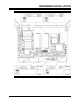
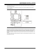
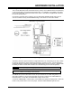
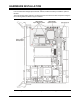
2.4 Front Panel Indicators and Controls
When installing or removing the board for the first time, or when checking its operation, it can be
very useful to note the behavior of the LEDs on the front panel. Figure 2-2 shows the location of
the LEDs, and their purpose is outlined below.
Figure 2-2 Front Panel Indicators and Controls
2.4.1 Run LED (R) Green
The run LED indicates that activity is occurring on the LPC bus or the 32-bit PCI bus. This allows
the user to quickly assess how active the busses are.
2.4.2 POST LED (P) Yellow
The POST LED is used to indicate that a power on self test has failed. This LED will also flash
when outputting sound on the speaker.
2.4.3 Ethernet Speed LED (SPD) Yellow
This LED indicates the operating speed of the front panel Ethernet interface, as follows:
• Off = 10Mbits/s
• Steady On = 100Mbits/s
• Flashing = 1000Mbits/s
2.4.4 Ethernet Link/Activity LED (LK/ACT) Green
This LED lights when connection has been made on the front panel Ethernet interface. It will flash
to indicate link activity, and during periods of high Ethernet activity the LED may switch off for
several seconds.
2.4.5 User LED (U) Red
This LED is available for use by user software. It is manipulated via an I/O register (see Section
9.2 for details). Alternatively, the User LED may be configured to light when the CPU reaches its
maximum specified operating temperature (see Section 11.2.3). In either mode, the User LED will
flash rapidly if the CPU Thermal Trip activates (see Section 11.2.6).
2.4.6 Hot-Swap LED (HS) Blue
This LED is used when the board is hot-swapped, and lights to indicate when the board can be
safely removed from the chassis.
2.4.7 EIDE Activity LED (I) Yellow
This LED lights when there is activity on the on-board EIDE interfaces or the SATA interfaces.