
Specifications

PP 41x/03x 2-1
2 HARDWARE INSTALLATION
2.1 General
This chapter contains general information on unpacking and inspecting the PP 41x/03x after
shipment, and information on how to configure board options and install the board into a
CompactPCI chassis.
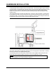
CAUTION: It is strongly advised that, when handling the PP 41x/03x and its associated
components, the user should at all times wear an earthing strap to prevent damage to the
board as a result of electrostatic discharge.
CAUTION: The heatsink used on the 2.0 GHz or 2.16 GHz processor variants of this
board will be hot during and after use. Care should be taken when handling the board.
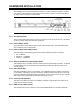
The list below outlines the steps necessary to configure and install the board. Each entry in the list
refers to a section in this chapter which will provide more details of that stage of the procedure. It
is recommended that the board is configured in the sequence below.
1) Unpack the board - see Section 2.2.
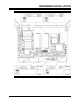
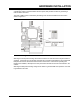
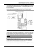
2) Locate and familiarize yourself with the front panel indicators and controls - see
Section 2.4.
3) Check that the board jumper settings match the required operating mode. See Section
2.3 for details of the default settings and where to find more information.
4) Fit a Compact Flash module if required - see Sections 2.5 and 2.7.
5) Fit the battery if necessary - see Section 2.6.
6) Fit a Mass Storage Module if required – see Section 2.7.
7) Change or fit DRAM SODIMMs if required – see Section 2.8.
8) Fit the PMC modules(s) if required - see Section 2.9.
9) Configure the board for the correct CompactPCI operating mode and for any external
sources for board or system resets - see Sections 2.10 and 2.11.
10) Install the board, using Hot Swap or non-Hot Swap procedures - see Section 2.12.