
Specifications


SPECIFICATIONS
PP 41x/03x A-15
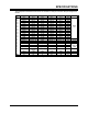
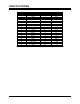
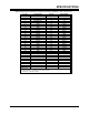
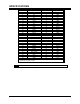
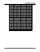
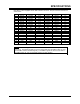
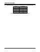
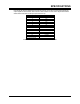
A.5.7 XMC Connector (J25) Pin-out
PMC Site 2 is also equipped with an XMC interface connector. The pin-out of this connector is
shown below.
Pin Row A Row B Row C Row D Row E Row F
1 PET0p0 PET0n0 +3.3V PET0p1 PET0n1 +5V
2 GND GND PULL DOWN GND GND RESET#
3 PET0p2 PET0n2 +3.3V PET0p3 PET0n3 +5V
4 GND GND PULL DOWN GND GND PULL UP
5 PET0p4 PET0n4 +3.3V PET0p5 PET0n5 +5V
6 GND GND PULL UP GND GND +12V
7 PET0p6 PET0n6 +3.3V PET0p7 PET0n7 +5V
8 GND GND PULL UP GND GND -12V
9 NC NC NC NC NC +5V
10 GND GND NC GND GND GA0
11 PER0p0 PER0n0 MBIST# PER0p1 PER0n1 +5V
12 GND GND GA1 GND GND PRSNT#
13 PER0p2 PER0n2 +3.3V PER0p3 PER0n3 +5V
14 GND GND GA2 GND GND MSDA
15 PER0p4 PER0n4 NC PER0p5 PER0n5 +5V
16 GND GND PULL UP GND GND MSCL
17 PER0p6 PER0n6 NC PER0p7 PER0n7 NC
18 GND GND NC GND GND NC
19 REFCLK+ REFCLK- NC WAKE# NC NC
Table A-11 XMC J25 Connector Pin-outs
NOTE: The terminology in the above table matches that used in the XMC specification,
VITA 42.3. The PET0xx signals are used to receive data from the XMC module (ie. they
are the XMC module’s transmit signals). The PER0xx signals are used to send data to
the XMC module (ie. they are the XMC module’s receive signals).