
Specifications


SPECIFICATIONS
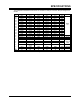
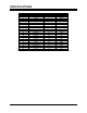
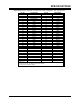
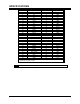
A-12 PP 41x/03x
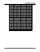
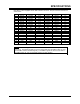
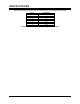
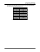
Pin No. Signal Name Pin No. Signal Name
1 +12V 2 NC
3 NC 4 NC
5 NC 6 GND
7 GND 8 NC
9 NC 10 NC
11 +3.3V†† 12 +3.3V
13 RST# 14 GND
15 +3.3V 16 GND
17 NC 18 GND
19 AD(30) 20 AD(29)
21 GND 22 AD(26)
23 AD(24) 24 +3.3V
25 IDSEL 26 AD(23)
27 +3.3V 28 AD(20)
29 AD(18) 30 GND
31 AD(16) 32 C/BE(2)#
33 GND 34 NC
35 TRDY# 36 +3.3V
37 GND 38 STOP#
39 PERR# 40 GND
41 +3.3V 42 SERR#
43 C/BE(1)# 44 GND
45 AD(14) 46 AD(13)
47 M66EN 48 AD(10)
49 AD(08) 50 +3.3V
51 AD(07) 52 NC
53 +3.3V 54 NC
55 PMC-RSVD 56 GND
57 PMC-RSVD 58 EREADY††
59 GND 60 NC
61 ACK64# 62 +3.3V
63 GND 64 +3.3V††
# denotes active low, † pulled high via 2.7kOhm resistor,
†† pulled high via 10kOhm resistor.
Table A-8 PMC J12 and J22 Connector Pin-outs
NOTE: Pins 58 and 64 are pulled high to suit Processor-PMC modules.