
Specifications


SYSTEM MANAGEMENT
11-2 PP 41x/03x
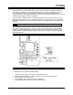
11.2 Thermal Management
The maximum power dissipation of the Intel Core Duo processor may sometimes be higher than
that of previous Intel Pentium M processors. Under typical load conditions, the heatsink (and
cooling airflow) will keep the processor die temperature within specification. However, if the board
is running CPU-intensive or stress software or if the airflow is inadequate, the heatsink alone may
not be able to prevent the processor overheating.
To ensure that the processor always operates within its thermal specifications, it includes several
thermal management and protection functions. Each of these is described below. A BIOS setup
option is used to select which functions are to be enabled. See Section 11.2.5 for further details.
11.2.1 Thermal Monitor 1 (TM1)
TM1 uses temperature sensors located near to the hottest parts of each CPU core on the
processor die. If a sensor detects a critically high temperature a thermal control circuit (TCC) will
modulate (i.e. alternately stop and start) the core clocks for the associated CPU core. This causes
the CPU core to halt for short periods and decreases its power consumption, which in turn lowers
the die temperature. Note that TM1 operates independently on each of the CPU cores.
The severity of the modulation will increase as the die temperature rises, up to a maximum of about
50%. The TCC will cease modulation when the die temperature has fallen to a non-critical value.
Intel individually calibrates the temperature sensors. The TM1 characteristics are also fixed by
Intel and cannot be modified.
The drawbacks of TM1 are that it starts to operate at a relatively low temperature (about 90°C) and
that it has a low modulation rate, which can produce undesirable software latencies.
TM1 is disabled after Reset and has to be enabled by the BIOS (see Section 11.2.5).
11.2.2 Thermal Monitor 2 (TM2)
TM2 uses the same temperature sensors as TM1. When the TM2 thermal control circuit is
triggered, the operating frequency and core voltage of both CPU cores will be reduced, causing the
power consumption to fall, which in turn lowers the die temperature.
Because a CPU under TM2 control operates continuously, the overall system performance for a
given reduction in power consumption is higher than TM1. System latency is also lower when
using TM2.
TM2 is disabled after Reset and has to be enabled by the BIOS (see Section 11.2.5).
11.2.3 CPU Thermal Trip
The processor chip also contains a thermal trip circuit. This is intended to protect the processor in
the event of a catastrophic cooling failure. If the die temperature reaches approximately 125°C, it
shuts down the processor core and asserts the THERMTRIP# signal. Logic on the board responds
to this assertion by removing the processor core voltage within a few milliseconds.
A power cycle (i.e. OFF then ON) is required to restore normal operation. The thermal trip circuit is
always operational and cannot be disabled.
NOTE: The User LED will flash rapidly (at a rate of approximately 4Hz) if the thermal trip
circuit activates.