
User Guide

Hardware and Software Design • Manufacturing Services
P a g e 8
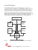
ports then the 4 FIFOs can be filled with the same pattern at the same time.
Fewer PCI cycles are required and less processing by the host.
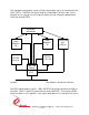
The transmit data rate can be derived from the 20 MHz on-board oscillator. The
normal transmitter data rate is 5 MHz (divide-by 4), other divisors are also
provided. The first COS port can be used as an alternate clock source as well as
the PCI clock. The max clock rate after division is required to be 20 MHz. The
receiver automatically adjusts to data rates.
The FIFOs always operate at the PCI clock frequency of 33 MHz to simplify testing
and operational functions. Loop-back is provided to allow confidence testing of an
installed board.
Thirty-two differential I/O are provided for the serial signals. The drivers and
receivers conform to the RS-485 specification (exceeds RS-422 specification).
The RS-485 input signals are selectively terminated with 100Ω. The termination
resistors are in two-element packages to allow flexible termination options for
custom formats and protocols. Optional pullup/pulldown resistor packs can also
be installed to provide a logic ‘1’ on undriven lines. The terminations and
transceivers are programmable through the Xilinx device to provide the proper
mix of outputs and inputs and terminations needed for a specific protocol
implementation. The COS directions are programmable via software. The Serial
interfaces are pre-programmed to their intended direction. The terminations are
programmable for all IO.
All configuration registers support read and write operations for maximum
software convenience, and all addresses are long word aligned.
The PMC BiSerial-II conforms to the PMC and CMC draft standards. This
guarantees compatibility with multiple PMC Carrier boards. Because the PMC
may be mounted on different form factors, while maintaining plug and software
compatibility, system prototyping may be done on one PMC Carrier board, with
final system implementation on a different one.
The PMC BiSerial-II uses a 10 mm inter-board spacing for the front panel,
standoffs, and PMC connectors. The 10 mm height is the "standard" height and
will work in most systems with most carriers. If your carrier has non-standard
connectors [height] to mate with the PMC BiSerial-II, please let us know. We may
be able to do a special build with a different height connector to compensate.