
User Guide

Hardware and Software Design • Manufacturing Services
P a g e 34
Applications Guide
Interfacing
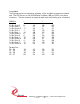
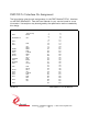
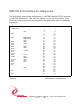
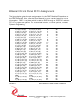
The pin-out tables are displayed with the pins in the same relative order as the
actual connectors. The pin definitions are defined with noise immunity in mind.
The pairs are chosen to match standard SCSI II/III cable pairing to allow a low
cost commercial cable to be used for the interface.
Some general interfacing guidelines are presented below. Do not hesitate to
contact the factory if you need more assistance.
Watch the system grounds. All electrically connected equipment should have a
fail-safe common ground that is large enough to handle all current loads without
affecting noise immunity. Power supplies and power-consuming loads should all
have their own ground wires back to a common point.
Power all system power supplies from one switch. Connecting external voltage to
the PMC BiSerial-II when it is not powered can damage it, as well as the rest of
the host system. This problem may be avoided by turning all power supplies on
and off at the same time. Alternatively, the use of OPTO-22 isolation panels is
recommended.
Keep cables short. Flat cables, even with alternate ground lines, are not suitable
for long distances. The PMC BiSerial-II does not contain special input protection.
The connector is pinned out for a standard SCSI II/III cable to be used. The
twisted pairs are defined to match up with the BiSerial II pin definitions. It is
suggested that this standard cable be used for most of the cable run.
Terminal Block. We offer a high quality 68-screw terminal block that directly
connects to the SCSI II/III cable. The terminal block can mount on standard DIN
rails. HDEterm68
[ http://www.dyneng.com/HDEterm68.html]
We provide the components. You provide the system. Safety and reliability can be
achieved only by careful planning and practice. Inputs can be damaged by static
discharge, or by applying voltage outside of the RS-485 devices rated voltages.