
User Guide

Hardware and Software Design • Manufacturing Services
P a g e 26
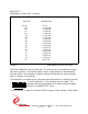
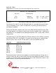
BIS2_DIR_TERM
[$38] BiSerial II Direction and Termination Register Port read/write
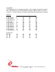
CONTROL DIR_TERM REGISTER
DATA BIT DESCRIPTION
13-0 DIRection 13-0 0 = read 1 = drive
29-16 TERMination 13-0 1 = terminated
FIGURE 13 PMC BISERIAL-II DIRECTION TERMINATION CONTROL BIT MAP
The direction for each of the 32 differential pairs is controlled through this port.
The port defaults to zero, which corresponds to tri-stating the drivers and no
terminations enabled.
Pull-up and Pull-down resistors built into some '485 interface devices may make
the signal appear to be driven (if open) when in the tri-stated mode. Enabling the
termination on a tri-stated line will yield approximately 2.5V on each side of the tri-
stated driver.
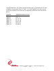
The base design of the PMC_BiSerial II_PS2 sets direction bits 0-8 high (outputs),
and direction bits 9-11 low (inputs). Currently the forced bits are read-write but
have no effect. Bits 12 and 13 are used to control the parallel port bits.
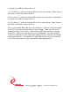
CONTROL CORRESPONDING IO BIT(S)
DIR_0..7 IO_0..7
DIR8 IO_8..11
DIR9 IO_12..15
DIR10 IO_16..19
DIR11 IO_20..23
DIR12 IO_24..27
DIR13 IO_28..31
Parallel termination resistors are supplied on each differential pair along with a
switch to allow the user to select which lines are terminated and where. In some
systems it will make sense to terminate the lines in the cable and in others it will
make sense to use the onboard terminations.