
User Guide

Hardware and Software Design • Manufacturing Services
P a g e 22
1
70
0
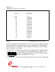
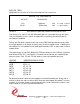
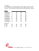
BIS2_STAT1
[$18] BiSerial II Status Port 1 read only
FIFO Status, Parallel Data In & Switch Register
DATA BIT DESCRIPTION
31-24 sw7-0
23 rx_fifo_full3
22 rx_fifo_full2
21 rx_fifo_full1
20 rx_fifo_full0
19 rx_fifo_mt3
18 rx_fifo_mt2
17 rx_fifo_mt1
16 rx_fifo_mt0
15 tx_fifo_full3
14 tx_fifo_full2
13 tx_fifo_full1
12 tx_fifo_full0
11 tx_fifo_mt3
10 tx_fifo_mt2
9 tx_fifo_mt1
8 tx_fifo_mt0
7-0 dat_in7-0
FIGURE 11 PMC BISERIAL-II STATUS 1 BIT MAP
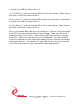
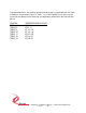
The Switch Read Port has the user bits. The user bits are connected to the eight
dip-switch positions. The switches allow custom configurations to be defined by
the user and for the software to identify a particular board by its switch settings
and to configure it accordingly.
The Dip-switch is marked on the silk-screen with the positions of the digits and the
'1' and '0' definitions. The numbers are hex coded. The
example shown would produce 0x12 when read [and shifted
down] from the BIS2_STAT1 port.
Tx_fifo_mt3-0 is '1' when the Transmit FIFO is empty for that channel. When data