
User Guide


Hardware and Software Design • Manufacturing Services
P a g e 20
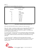
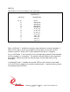
BIS2_STAT0
[$14] BiSerial II Status Port 0 read status, write clear
STATUS 0
DATA BIT DESCRIPTION
31-25 Spare
24 interrupt status
23 f7_intr_lat
22 f6_intr_lat
21 f5_intr_lat
20 f4_intr_lat
19 f3_intr_lat
18 f2_intr_lat
17 f1_intr_lat
16 f0_intr_lat
15 r7_intr_lat
14 r6_intr_lat
13 r5_intr_lat
12 r4_intr_lat
11 r3_intr_lat
10 r2_intr_lat
9r1_intr_lat
8r0_intr_lat
7 rx3_intr_lat
6 rx2_intr_lat
5 rx1_intr_lat
4 rx0_intr_lat
3 tx3_intr_lat
2 tx2_intr_lat
1 tx1_intr_lat
0 tx0_intr_lat
FIGURE 10 PMC BISERIAL-II STATUS REG 0 BIT MAP
When Interrupt Status is read as a one, it indicates that one or more latched
interrupt conditions are true. In order for an actual system interrupt to occur, the
interrupt enable for that condition and the Master Interrupt Enable must both be
asserted. When this bit is zero, no interrupt conditions are pending.