Contents Introduction Page 2 Installation Page 3 Instrumentation Page 7 Operation / Function Page 9 Programming Page 18 Appendix Page 21 Wire Diagram Page 22 Warranty Page 24 All Rights Reserved. Reproduction by any means, electronic or mechanical including photocopying, recording or by any information storage and retrieval system or translation in whole or in part is not permitted without written authorization from Signal Dynamics Corporation. Copyright © Signal Dynamics Corporation.
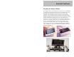
Introduction LINX™ Network Bus Electrical System System Overview: Simpler, easier installation and comprehensive rider information; these are the some of the basic advantages of the LINX™ Network Bus Wiring System. As you read this manual you will realize the significant improvements and advanced features that this system provides over conventional wiring harnesses. Additionally, updates, knowledge base and Q&A for this system will be updated and posted on the LINX™ web-site as they occur at www.
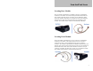
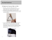
Installation Locating Rear Module The rear module is identified by its’ Black Connector, and should be located in an area that is close to the battery and Starter Solenoid, and also central to all of the devices it connects to. The module is splash proof, but should be mounted in an area that has some protection from water and heat. Under the seat on the battery box is usually a good location. The module mounts with the enclosed double sided tape.
Installation Installing switch cubes The switch cubes are designed to fit a 1” handlebar, and connect to the front brake switch, and clutch switch (optional). Installing the switch cubes involves drilling a hole in the handlebar where the switch cube will be located, and another where the wires will connect to the display module.
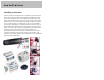
Installation Installing the Display Module The display module can be mounted either above or below the handlebar by attaching the backing plate mounting tab to a handlebar clamp (not included). The wires from the switch cubes will come out of the handlebars, into the display housing, and plug into the appropriate connector. The data wire from the front module is routed to the display module and plugged into the appropriate connector.
Installation To Replace the Connector End on a Cable. 1. 2. 3. 6 Strip about 1” of the outer insulation with an RJ-45 stripper/crimping tool, the inner insulation does not need to be stripped. These tools are commonly used to crimp computer network cables, and are avalible at most electronic stores. Insert the wires into the low profile connector. Be sure the blue wire is to your left with the clip of the connector away from you, and the connector pointing up.
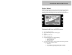
Instrumentation Display Module: When the system is powered-on, a self-test will run and if any faults are noted, they will be displayed. After this, the logo will be displayed for 3 seconds, and then the module will enter the operational mode. The following items will be displayed on the screen in the operational mode: Information & Icons on LCD Screens: • • • • • • • Speed (in MPH or KPH). Engine RPM (digital readout and bar graph). Clock. High Beam “ON” Icon. Bike in “Neutral” Icon.
Instrumentation • • Temperature and Voltage. System Alert text message. (If Present) Indicators: The indicator icons are located to the left and right sides of the LCD display screen. When they are active they are back-lit with LED lighting. 8 • Turns Signal Direction Arrows – Located at the top and to the left and right of the LCD display screen. These indicators are backlit with green LED’s and will flash when the turns signals or hazards flashers are activated.
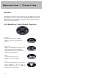
Operation / Function Front (Tank) Module The following outputs and operations are controlled by the Front Module: • • • • • • Ignition Compression Release NOS solenoid (optional) Left & Right Front Turns Signals Headlight High & Low beam Horn Rear Module The following inputs/outputs and operations are controlled by the Rear Module: • • • • • • • • • Speedometer Input (Transmission) Tachometer Input (Cam / Crank Sensor or Ignition Coil) Neutral Oil Pressure Rear Brake Input Rear Brake Light Right & Left R
Operation / Function Switches: The handlebar switches are designed for easy installation or removal with plug-in connector. They are also LED back-lit for easier button identification during night time conditions. They provide a positive tactile click when depressed. Left Handlebar Switch Module Functions Left Turn Starts or cancels left turn signal function. (See turn signal function below) High / Low Toggles the headlight from high to low beam.
Operation / Function Right Handlebar Switch Module Functions Right Turn Starts or cancels right turn signal function. (See turn signal function below) Start Will activate the engine starter solenoid circuit if: the Run/Kill switch is set to Run, the bike is in neutral, and the engine is not running (RPM =0). Run / Kill Will allow the bike to start if the Run function is selected. Will kill the engine or prevent a start if the Kill function is selected.
Operation / Function Initial LINX™ Power-UP & Starting Key Switch Operation: When the key switch is turned on, power is applied to the LINX™ system and a self-test will run. If any faults are noted, they will be displayed on the LCD screen. After this, a Logo and VIN # (if programmed) will be displayed for 3 seconds, and then the LINX™ system will enter the operational mode.
Operation / Function the start button on the right handlebar switch to initiate the engine starter. The starter motor can not be accidentally engaged if the LINX™ system recognizes that the motor is already running. If a start is necessary while the bike is rolling, a start with the electrical starter motor can be accomplished above 5 MPH, by assuring the Run/Kill switch is in the “Run” position and the clutch is pulled in. To complete the start, press the start button.
Operation / Function Information & Alert Conditions Text information window: The Text information window is located at the bottom of the LCD screen. To toggles between the following items, press the (#) key on the right handlebar switch. • • • • • Odometer Trip 1 (Reset by pressing the # key for 3 seconds) Trip 2 (Reset by pressing the # key for 3 seconds) Temperature and Voltage. System Alert text message.
Operation / Function Lighting Marker Lights: Turn Signal Lights also function as marker lights. This function enables single intensity incandescent or LED bulbs to have a marker light feature. Headlight Features & Operation: Low Beam When the key switch is first turned on, the headlight is automatically selected to low beam to conserve battery power. When an engine start is initiated, the headlight is automatically cycled to “off “. However, the turn signal/marker lamps remain “on”.
Operation / Function Turn Signal Function: The turn signal selection buttons are located on the left and right handle bar switch cubes. The turn signals are activated by pressing the appropriate button. The turn signals will flash for 7 seconds then automatically cancel. The number of flashes or seconds remaining will be displayed in the information window of the LCD Screen. If more flash time is required simply press and hold the turn signal button, and the number of seconds or flashes increases.
Operation / Function • Brake Lights: When the brakes are applied and the motorcycle is stopped, the brakes remain on until the bike accelerates. This will also cause the turn signals to continue to flash 10 seconds after the bike accelerates. Circuit Protection The LINX™ system does not require external fuses for circuit protection. The sophistication of this system automatically checks each circuit thousands of times per second to assure it is operating properly.
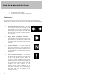
Programming Program Mode: To enter the program mode, the bike’s run/kill switch must be in “kill” position. After selecting “kill”, the press ( * ) and ( # ) together for 5 seconds. The program menu will then pop-up on the LCD screen. The following keys are used to program the module: Key Function High / Low -Scroll Up Horn -Scroll Down (*) -Select Programmable Items: • Screen Contrast – To adjust the contrast of the display.
Programming • Vehicle Identification Number - Set or View VIN# (Vin # may only be set once on some bikes). • View Logs - This will display a history of “events” and “faults” encountered by the system. This log erases the oldest message when the amount of space for storage is maxed out. Faults are not erasable, but events are. The format for the error log is: Time / Date of Condition Condition Text Message • Clear Event Log - Used to clear event logs. Note: error logs cannot be erased.
Programming • Voltage/Temperature are displayed) This will take you to a screen prompting you to press the # button at the beginning of a measured mile. When you pass the beginning mile marker press the # button. The screen will then prompt you to press the # button at the end of the ending mile marker. When you do this, the speedometer will be calibrated and return to the operating mode.
Appendix System Specification: System Power 12VDC 30Amps Operating Temperatures 32°F to 122°F (0°C to 50°C) Physical Size Front / Rear Module 2.0” X 3.0” x 1.5” Display Module 2.0” X 3.5” X 1” Maximum Amperage Load: Headlight High Beam Low Beam Turn Sign/Marker Light Brake/Running Light Horn Starter Solenoid NOS Solenoid Compression Release Ignition Coil 10A 10A 5A each 5A 5A 100A Momentary (50A Continous) 5A 5A 5A Note: The LINX™ system draws a very small amount of current in the “Off” mode.
Warranty One Year Limited Warranty Signal Dynamics Corporation warranties this product at time of purchase to be free from defects in materials or workmanship to the original purchaser. Signal Dynamics Corporation's obligation under this warranty is limited to repairing or exchanging the unit if the unit is returned, postage prepaid, to Signal Dynamics Corporation within one (1) year from date of purchase. The warranty is void if the unit has been incorrectly installed, damaged, or tampered with.