Model 122A21 Helium Bleed, ICP® Dynamic Pressure Sensor Installation and Operating Manual For assistance with the operation of this product , contact the Pressure Division of PCB Piezotronics, Inc. Division toll-free 888-684-0015 24-hour SensorLineSM 716-684-0001 Fax 716-686-9129 E-mail pressure@pcb.
Warranty, Service, Repair, and Return Policies and Instructions The information contained in this document supersedes all similar information that may be found elsewhere in this manual. Total Customer Satisfaction – PCB Piezotronics guarantees Total Customer Satisfaction. If, at any time, for any reason, you are not completely satisfied with any PCB product, PCB will repair, replace, or exchange it at no charge.
Materials Authorization (RMA) Number. This RMA number should be clearly marked on the outside of all package(s) and on the packing list(s) accompanying the shipment. A detailed account of the nature of the problem(s) being experienced with the equipment should also be included inside the package(s) containing any returned materials. PCB for a complete statement of our warranty. Expendable items, such as batteries and mounting hardware, are not covered by warranty.
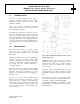
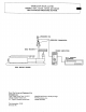
OPERATION MANUAL FOR MODELS 122A, 122A21, 122A22, and 122A24 HELIUM BLEED PRESSURE SENSOR 1.0 INTRODUCTION The series of sensors described in this guide is designed to measure dynamic pressure in intense thermal environments typified by rocket engine combustion chambers. These sensors feature acceleration-compensated piezoelectric pressure probes, mounted in a conical end seal helium bleed adaptor.
OPERATION MANUAL FOR MODELS 122A, 122A21, 122A22, and 122A24 HELIUM BLEED PRESSURE SENSOR 3.0 INSTALLATION 4.0 2 OPERATION Prepare mounting port in accordance with instructions on installation drawing 122-1010-90. 4.1 Inspect the mounting port for burrs and tool marks at the conical seal surface. For the 122A Charge Output Model, it is only necessary to select the proper range on the charge amplifier and proceed with the measurement.
OPERATION MANUAL FOR MODELS 122A, 122A21, 122A22, and 122A24 HELIUM BLEED PRESSURE SENSOR 4.3 OPERATION - ICP MODELS 122A21, A22, and A24 5.1 CHARGE MODEL 122A Consult Guide G-0001B for a complete description of the low-impedance concept in instrumentation. To calibrate this model, install in pressure port of dead weight tester and apply various static pressures recording corresponding outputs at each pressure of interest.
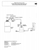
OPERATION MANUAL FOR MODELS 122A, 122A21, 122A22, and 122A24 HELIUM BLEED PRESSURE SENSOR 6.0 GROUND ISOLATION All sensor probes in this series are mounted in an "OFF GROUND" configuration. That is, the probe body is electrically insulated from the sensor outer body to avoid ground loops. 7.0 MAINTENANCE AND REPAIR The sealed construction and miniature size of these sensors make field repair impractical. The helium filter element should be cleaned should the flow rate decrease.
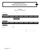
OPERATION MANUAL FOR MODELS 122A, 122A21, 122A22, and 122A24 HELIUM BLEED PRESSURE SENSOR 7 Test Report Helium Flow Test and Burst Test Sensor Model ________________________ S/N __________________________ Initial Calibration: Input (PSI) System Output (V) 500 1000 1500 2000 2500 3000 1000 1500 2000 2500 3000 Burst Test to 5000 PSI - Failed Final Calibration: Input (PSI) System Output (V) 500 Helium Flow Test: Input Pressure _________ PSIG Flow Rate _________ SCFH Drawing number: 21089