Model 103B11 ICP® Dynamic Pressure Sensor Installation and Operating Manual For assistance with the operation of this product , contact the Pressure Division of PCB Piezotronics, Inc. Division toll-free 888-684-0015 24-hour SensorLineSM 716-684-0001 Fax 716-686-9129 E-mail pressure@pcb.
Warranty, Service, Repair, and Return Policies and Instructions The information contained in this document supersedes all similar information that may be found elsewhere in this manual. Total Customer Satisfaction – PCB Piezotronics guarantees Total Customer Satisfaction. If, at any time, for any reason, you are not completely satisfied with any PCB product, PCB will repair, replace, or exchange it at no charge.
Materials Authorization (RMA) Number. This RMA number should be clearly marked on the outside of all package(s) and on the packing list(s) accompanying the shipment. A detailed account of the nature of the problem(s) being experienced with the equipment should also be included inside the package(s) containing any returned materials. PCB for a complete statement of our warranty. Expendable items, such as batteries and mounting hardware, are not covered by warranty.
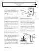
OPERATION MANUAL FOR MICROPHONE Series 103A 1.0 DESCRIPTION The Series 103A microphones are high-sensitivity pressure sensors featuring miniature size, built-in solid state electronics and acceleration compensation. The Model 103A (see installation drawing) has pigtail leads extending radially from the side of the unit and has a nominal sensitivity of 1500 mV/psi.
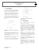
OPERATION MANUAL FOR MICROPHONE Series 103A 2 The result is a two-wire system, precluding the need for multi-conductor cabling. A second diaphragm, located behind the pressure diaphragm and attached to another bimorph bender crystal acting in opposition to the pressure crystal, provides acceleration compensation to the Series 103A Sensors. VIEW FROM DIAPHRAGM END WHITE TO READOUT BLUE (N.C.) BLACK 3.
OPERATION MANUAL FOR MICROPHONE Series 103A Refer to Guide G-0001B for tips on power and signal utilization. NOTE: The internal low-noise amplifier in the Model 103A, A02, A11 and A12 differ from the standard ICP® amplifiers described in Guide G0001B in that the turn-on (or bias) voltage is nominally +4 volts. Proper turn-on for Models 103A02, A11 and Al 2 will not give center scale reading on the fault monitor meters found on most PCB signal conditioners but will show a reading of approximately 20% of F.