Operating Manual for LCD DIGITAL PROPORTIONAL RADIO CONTROL SYSTEM WWW.DYNAM-RC.
Catalog Function of Transmitter Contents Specifications Notice for flying Notification before Using Description of four flying modes Transmitter particular introduce Receiver Operation for transmitter and servo Adjustmen order Charge method of battery Explaination for technical words 2 03 03 03 04 05 06 07 08 09~10 11 11 12
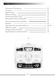
Thanks for purchasing RACON X6 radio control set. For safe use, please read this manual before using carefully. Any damage or loss to radio control set and model due to inproper use will not be shouldered by noreum Machi. Function of Transmitter RACON X6 is a newly developed 6 channel proportional transmitter with four flying mode installed: A(aeroplane mode);V( V tail mode); C(CCPM helicopter mode);H(helicopter mode) The switch between each mode is very convenient.
Notice for flying Please do not fly in the same area with simiar f requency, or that can cause crash. Please do not fly in the rain or strong wind. The water can sink into the transmitter which can cause out of control, leading to crash. The shortened antenna may cause the short range of signal, please pull the antenna to the end. Please straighten the wire of receive.
Notification before using Indications of special signs please pay more attention to signs in this manual and safety while using Show Logo Meanings WARNING I inproper operation may cause injury or hurt CAUTION I inproper operation may cause injury or hurt Storage note Please do not place the radio control se in the below situation: hot or cold (60 C above or - 10 C below) under the sunshine long time moist condition dusty place vibration condition Long time without using, please pick up batteries f ro
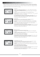
Description of four flying modes RACON X6 with four flying mode installed: A(aeroplane mode);V( V tail mode);C(CCPM helicopter mode);H (helicopter mode) the switch between each mode is very convenient. There is a reverse switch for CH1,CH2,CH4 and Ch6 separately. The LCD on the transmitter can show voltage of transmitter, channel status, flying mode and flying time. It has a function of auto-alarm for low voltage. 05:08 CH A MODEL 08:57 9.
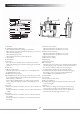
Transmitter particular introduce A B C E G K M O Q I H F Y D P J L N R S A: Antenna B: LCD(Liquid Crystal Display) 1)To indicate the battery voltage of transmitter. 2)To show the situation of channels whether it is reversed. 3)To show the flying time. 4)To indicate flying mode. 5)To indicate the status of lock and unlock. C: Tiny Mix 1 D:Tiny Mix 2 E:Switch 1 this switch is for ch5 that can be used for aerial camera, collapsible landing gear and shift between gyro mode and gain, etc.
Receiver Function FM FM 6 Channel single conversion 8 6 Channel single conversion
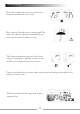
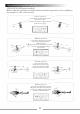
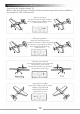
Operation for transmitter and servo Operation for helicopter (mode 1) Before adjusting, please be familiar with transmitter operation and servo(Before description in case of all neutral) Aileron operation joystick for aileron left forward plane moves left joystick for aileron right forward plane moves right Elevator operation joystick for elevator up forward tail is up, and plane will go down forward joystick for elevator down forward tail is down, and plane will go up forward Throttle operation joystick
Operation for transmitter and servo Operation for airplane (mode 1) Before adjusting, please be familiar with transmitter operation and servo(Before description in case of all neutral) Aileron operation joystick for aileron right forward the right aileron up and left aileron down and vice versa Elevator operation climb up forward operation joystick for elevator is down forward, the elevator is up, and tail is down, then the plane will climb up, and vice versa Operation for throttle joystick for throttle i
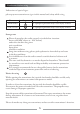
Adjustment order Open the battery bay, and range the 8 cells AAA battery into the battery bay, then close the bay. Before adjustment, change the reverse switch to the lower position(nor). Open the transmitter and the receiver, and do the following steps: 1.check every servo’s movement and make sure every movement of control arms and servo arms is correct if not, please change the switch for reverse. 2.
Explainaction for technical words 12