5450 NW 33rd Ave, Suite 104 Fort Lauderdale, FL 33309 3211 Fruitland Ave Los Angeles, CA 90058 UM-200 2-Channel Monitor Installation and Operation Manual Rev.
IMPORTANT - PLEASE READ BEFORE PROCEEDING! The Dynalco model UM-200 is designed for reliable and rugged operation on engines, turbines, pumps, compressors and other machinery for accurate process measurement and protection. This product has been designed and tested to meet the demands required in many industrial and hazardous locations meeting critical CSA standards. The performance is directly related to the quality of the installation and knowledge of the user in operating and maintaining the instrument.
System Overview The Dynalco UM-200 is capable of reading up to 2 input channels, calculating differential value and providing an alarm / shutdown output. Basic operation: The UM-200 will be in “stopped” mode until a run indication is sensed. This is selectable as either a contact closure or magnetic pickup input. Once “running” mode is sensed, the UM200 will read both inputs at a rate of 100 msec per channel.
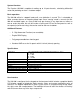
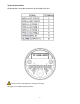
Installation The UM-200 is designed to be panel mounted. The dimensions are shown below. The UM-200 has a bracket for securing into the panel.
Terminal Connections All connections are made to terminals on the back of the unit. Terminal screws to be tightened to 8 inch-pounds torque. See page 10 for complete wiring information.
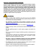
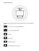
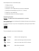
Programming Overview All programming is accomplished through the front keypad. Below is a brief description of each key.
Initial configuration consists of the following steps: 1) Enabling each input 2) Defining each input type 3) Defining min. & max. display values for any current or voltage inputs 4) Defining measurement display units (PSI, mV, F, C, H20, etc) 5) Setting over / under setpoint trips 6) Setting either latching or non-latching for output trip Programming Instructions Important: The UM-200 must first be programmed prior to operation.
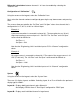
Configuration of “Run Signal” Using the arrows on the keypad, select the “Run Signal” icon. There are (3) run types available. The definitions are as follows: None: No run indication required. Monitoring is always active. RPM: Monitoring is active when signal received from magnetic pickup. Digital: Monitoring is active when contact closure (connection to ground) is sensed. To select run signal type, use the up / down arrows to select, then press enter.
Differential calculations between channels 1 & 2 are also enabled by selecting the “Channel” icon. Configuration of “Calibration” Using the arrows on the keypad, select the “Calibration” icon. Next, select the channel number to configure by pressing the up / down arrows and pressing enter. The screens allow you to define the “Cal Zero” and “Cal Span” values for a channel that is configured for 0-1 V, 0-5 V, 0-10 V or 4-20 mA input. Example 1: A pressure transmitter is connected to channel # 1.
Note that you are selecting the default layout type. You will be able to change the layout during normal operation by pressing the left / right arrows. Operation Once programmed, the UM-200 will begin scanning the enabled channel inputs and will initiate alarms based on over / under threshold values configured for each channel. It is not necessary to define alarm threshold values for both channels as they may be for monitoring only.
10