DYNALCO SW-100 Speed Switch / Transmitter Operating Manual 3690 NW 53rd Street • Fort Lauderdale, FL 33309 • Ph 954-739-4300 • Fax 954-486-4968 • www.dynalco.
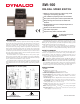
SW-100 DIN-RAIL SPEED SWITCH z Simple on-line trip frequency setting (using actual input signal or frequency generator) z User settable trip frquency from 0.
SPECIFICATIONS (Cont’d) ELECTROMAGNETIC COMPATIBILITY Immunity to EN 50082-2 Electrostatic discharge EN 61000-4-2 5. CONTROL INPUTS: Active low (VIL = 0.5 V max.) internally pulled up to 5 VDC through a 100 KΩ resistor (ISNK = 50 μA). Response Time = 1 msec. Alarm Reset: Unlatches the relay when pulled to common while the input frequency is in the release region. Alarm Override: Causes the SW-100 to unconditionally release the relay when pulled to common. 6.
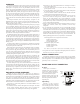
OVERVIEW Listed below are the recommended methods of connecting the shield, in order of their effectiveness. a. Connect the shield only at the rail where the unit is mounted to earth ground (protective earth). b. Connect the shield to earth ground at both ends of the cable, usually when the noise source frequency is above 1 MHz. c. Connect the shield to common of the unit and leave the other end of the shield unconnected and insulated from earth ground. 2.
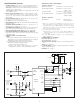
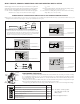
INPUT CIRCUITS, SENSOR CONNECTIONS AND CONFIGURATION SWITCH SET-UP The SW-100 Speed Switch uses a comparator amplifier connected as a Schmidt trigger circuit to convert the input wave form into the pulse form required for proper circuit operation. Three set-up switches are used to configure the input circuit to accept signals from a wide variety of sources, as follows: S1 - ON: Connects a 1 KΩ pull-down resistor for sensors with sourcing outputs. (Maximum sensor output current is 24 mA @ 24 VDC output.
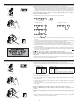
RELAY INDICATION Overspeed: The Relay LED (red) turns on to indicate the input signal has exceeded the trip frequency. Underspeed: The Relay LED (red) turns on to indicate the input signal is below the trip frequency setting. Invalid Entry during Set-up: The Input LED (green) and the Relay LED (red) alternately blink until a valid entry is made.
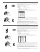
3.0 Set Trip Frequency Using The Rotary Switch 4 GREEN INPUT LED BLINKS 5 6 7 Step 3.1 IN 3.1 Place DIP switch 4 to the ON position and DIP switches 5, 6, and 7 as shown. 3.2 The Green input LED blinks the existing Trip Frequency setting, pauses and repeats. Six full digits of numerical information blink with a 2 sec. pause between digits and a 4 sec. pause at the end, before repeating. The first five digits are the existing Trip Frequency magnitude.
5.0 Set Relay Trip Point (Offset) 4 GREEN INPUT LED BLINKS 5 6 For Overspeed operation, the Relay Trip point is internally set to the Trip Frequency plus the Offset value. For Underspeed operation, the Relay Trip point is internally set to the Trip Frequency minus the Offset value. The Offset value is equal to the Trip Frequency multiplied by the selected Offset percentage. Example: The Offset value is calculated as shown below. Trip Frequency = 250 Hz Rotary Switch Setting = 4 (2.
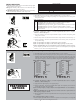
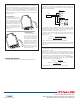
INSTALLATION The unit is equipped with a universal mounting foot for attachment to standard DIN style mounting rails, including G profile rail according to EN50035 - G32 , and top hat (T) profile rail according to EN50022 - 35 x 7.5 and 35 x 15. The unit should be installed in a location that does not exceed the maximum operating temperature and provides good air circulation. Placing the unit near devices that generate excessive heat should be avoided.